 What is a high frequency inverter?In many applications, it is important for an inverter to be lightweight and of a relatively small size. This can be achieved by using a High-Frequency Inverter that involves an isolated DC-DC stage (Voltage Fed Push-Pull/Full Bridge) and the DC-AC section, which provides the AC output.
What is a bridge type inverter?The simplest form of an inverter is the bridge-type, where a power bridge is controlled according to the sinusoidal pulse-width modulation (SPWM) principle and the resulting SPWM wave is filtered to produce the alternating output voltage. In many applications, it is important for an inverter to be lightweight and of a relatively small size.
What is HF bridge inverter?An HF bridge inverter produces a 50Hz modulated SPWM HF wave whose voltage level is boosted by an HF transformer. An active rectifier rectifies Fig.1Low-frequency inverter design methodsaBridge-type inverterbInverter design consisting of a DC/DC converter and power bridge.
What is a sg3525 based H-bridge inverter?The SG3525-based H-bridge inverter circuit is a reliable and efficient solution for converting DC voltage to AC power. With features such as voltage regulation and low battery protection, it is suitable for powering a wide range of devices.
How do bridge rectifiers work?The bridge rectifiers (D1. D4) convert the square-wave signal back to DC voltage and store it in the intermediate circuit (L1+C2). A second full bridge (S5. S8) then generates a 50 Hz AC voltage, which is smoothed to a sinusoidal 50 Hz AC voltage via the chokes (L2+L3) before being fed into the public grid. Figure 2-1.
Does HF bridge inverter reduce transformer losses?In an alternative version, the HF bridge inverter produces an HF PWM wave, thus reducing the transformer losses [4, 5]. In the last two design methods the power flow is uni- directional from the DC input source to the AC output load because of the diode rectifier. However, in applica- tions involving renewable energy source systems wh
What is a high frequency inverter?In many applications, it is important for an inverter to be lightweight and of a relatively small size. This can be achieved by using a High-Frequency Inverter that involves an isolated DC-DC stage (Voltage Fed Push-Pull/Full Bridge) and the DC-AC section, which provides the AC output.
What is a bridge type inverter?The simplest form of an inverter is the bridge-type, where a power bridge is controlled according to the sinusoidal pulse-width modulation (SPWM) principle and the resulting SPWM wave is filtered to produce the alternating output voltage. In many applications, it is important for an inverter to be lightweight and of a relatively small size.
What is HF bridge inverter?An HF bridge inverter produces a 50Hz modulated SPWM HF wave whose voltage level is boosted by an HF transformer. An active rectifier rectifies Fig.1Low-frequency inverter design methodsaBridge-type inverterbInverter design consisting of a DC/DC converter and power bridge.
What is a sg3525 based H-bridge inverter?The SG3525-based H-bridge inverter circuit is a reliable and efficient solution for converting DC voltage to AC power. With features such as voltage regulation and low battery protection, it is suitable for powering a wide range of devices.
How do bridge rectifiers work?The bridge rectifiers (D1. D4) convert the square-wave signal back to DC voltage and store it in the intermediate circuit (L1+C2). A second full bridge (S5. S8) then generates a 50 Hz AC voltage, which is smoothed to a sinusoidal 50 Hz AC voltage via the chokes (L2+L3) before being fed into the public grid. Figure 2-1.
Does HF bridge inverter reduce transformer losses?In an alternative version, the HF bridge inverter produces an HF PWM wave, thus reducing the transformer losses [4, 5]. In the last two design methods the power flow is uni- directional from the DC input source to the AC output load because of the diode rectifier. However, in applica- tions involving renewable energy source systems wh
Jan 15, 2018 · The term Active Front End Converter (AFC) refers to the power converter systemconsisting of the line-side converter with an active switch such as IGBTs, the dc
Nov 8, 2023 · In an active front-end rectifier based on cascaded H-bridge high-voltage inverter, the DC link voltage of the submodule often fluctuates due to load uncertainties, and the
Dec 23, 2020 · 3 Conventional rectifier topologies for high-current variable-voltage applications Diode- and thyristor-based recti ers are most commonly used for fi high-power high-current
Sep 30, 2020 · The circuit configuration consists of high DC input voltage, DC-link capacitors, novel multi-level conversion unit, high frequency flyback
Jul 9, 2024 · High-frequency bridge rectifiers are used in high-frequency power systems and usually use fast recovery diodes to meet the needs of switching
May 28, 2021 · Full-wave bridge rectifiers are widely used in power electronics for ac-dc conversion. In most of the conventional rectifier analysis, the diodes were modeled as
Mar 23, 2023 · The three-level Vienna rectifier is a very attractive boost-type power factor converter (PFC) because of its lower total harmonic distortion (THD) of input current and high
Jan 24, 2024 · This technical note introduces the working principle of the Active Front End and presents an implementation built with the TPI 8032.
Feb 27, 2021 · In which we are developing an inverter which is to be light in weight, compact and highly energy efficient. This can possible with the help of High Frequency Inverter; hence we
This paper examines the current state of Home Energy Management Systems (HEMSs), highlighting the key role of the single-phase bidirectional rectifier
Oct 29, 2015 · In many applications it is important for an inverter to be of relatively small size and lightweight. This can be achieved by using a high-frequency (HF) link inverter topology. A
Apr 1, 2023 · Here H-bridge circuit converts battery DC voltage into AC using high frequency PWM (6 kHz to 20 KHz) thus feeding the 50-Hz transformer which Boost it to 120V/220V AC.
May 11, 2022 · A CIB IGBT module has a diode based three phase rectifier front end, IGBT based three-phase inverter output stage and a brake chopper stage all integrated within a single
Mar 3, 2023 · The full-bridge converter topology consists of a DC power source, an H-bridge MOSFET configuration, a high frequency transformer, a full bridge diode rectifier, a low pass
Feb 4, 2019 · The load current and the supply frequency are generally outside the control of the designer of the rectifier system but the number of peaks per input cycle can be affected by the
Nov 1, 2018 · To make the proposed CF-DHB operate at the maximum power point (MPP), we use the incremental conductance method that offers smooth transition to MPP. Experimental
Nov 8, 2023 · In an active front-end rectifier based on cascaded H-bridge high-voltage inverter, the DC link voltage of the submodule often fluctuates due to load uncertainti
Apr 1, 2023 · In many applications, it is important for an inverter to be lightweight and of a relatively small size. This can be achieved by using a High-Frequency Inverter that involves an
Aug 1, 2024 · Therefore, this also creates hardware computing conditions for simulating the high-frequency switching action of switching elements in the three-phase IGBT full-bridge inverter
Apr 28, 2022 · phase four-wire topologies to be applied into high modulation index operating conditions. devices are to be used for developing high-frequency three-phase rectifier/inverter
Aug 17, 2019 · "A Comprehensive Design Approach for a Three-Phase High-Frequency Single-Switch Discontinuous-Mode Boost Power Factor Corrector based on Analyticaly Derived
Apr 18, 2025 · This study presents a novel multilevel inverter drive topology, which is powered by a single battery source and uses a small, affordable high-frequency link (HFL) to generate
In this study, a hybrid approach is presented for the asymmetric Cascaded H-Bridge (CHB) MLI topology. Two switches are added to the High Frequency Link (HFL) circuit to allow the HFL
Aug 12, 2025 · Generally a RF- SMPS can be considered in two parts, an inverter and a recti- fier. The inverter stage converts DC voltage to an RF sinusoidal current. The rectifier stage
Apr 25, 2025 · This paper presents a novel fault-tolerant approach for cascaded H-bridge inverters with a full-bridge single-phase rectifier cell structure. Upon
Apr 1, 2021 · Such drive systems are usually fed by semiconductor switch-based inverters, which, unlike balanced pure sine-wave AC sources, produce large-amplitude, high-frequency
Aug 3, 2025 · 1.2 Switching Mechanisms and Waveforms Switching Sequence in Full-Bridge Inverters The full-bridge inverter operates by controlling four switching devices (typically
The front end for the system is a regenerative single phase full bridge IGBT inverter along with an AC reactor. Steady-state design considerations are explained, and control techniques for unity
Apr 28, 2022 · Keywords: Critical conduction mode, digital control, high frequency, silicon carbide, soft switching, three-phase rectifiers/inverters.
Dec 1, 2024 · Additionally, as shown in Fig. 1 (b), VSI''s high-frequency switching-action needs a considerable amount of power-input with rich harmonic-current at high-speed and causes
Jan 9, 2025 · The SG3525-based H-Bridge inverter circuit converts low-voltage DC into high-voltage AC, making it ideal for use in applications like renewable
Apr 16, 2024 · WHY ARE THREE−PHASE PFC TOPOLOGIES ON DEMAND? Three−phase Power Factor Correction (PFC) systems (or also call Active Rectification or Active Front−End
Mar 23, 2023 · Abstract—Future three-phase ac-dc converter systems ideally allow for bidirectional power flow, provide high-frequency isola- tion, and feature buck-boost capability.
Sep 30, 2020 · High frequency square wave across the primary and secondary modulated at switching frequency The high frequency signals are phase shifted with respect to each other
Mar 15, 2022 · 1: Introduction Battery chargers for electric vehicles require galvanic isolation between the grid connection and the batteries. Therefore, an
Jul 26, 2022 · Schematic diagrams [3] and [4] of (a) coupled inductor structure for reducing the HF current ripple; (b) half-bridge active filter, which compensates for the low-frequency harmonic
In many applications, it is important for an inverter to be lightweight and of a relatively small size. This can be achieved by using a High-Frequency Inverter that involves an isolated DC-DC stage (Voltage Fed Push-Pull/Full Bridge) and the DC-AC section, which provides the AC output.
The simplest form of an inverter is the bridge-type, where a power bridge is controlled according to the sinusoidal pulse-width modulation (SPWM) principle and the resulting SPWM wave is filtered to produce the alternating output voltage. In many applications, it is important for an inverter to be lightweight and of a relatively small size.
An HF bridge inverter produces a 50Hz modulated SPWM HF wave whose voltage level is boosted by an HF transformer. An active rectifier rectifies Fig.1Low-frequency inverter design methods aBridge-type inverter bInverter design consisting of a DC/DC converter and power bridge
The SG3525-based H-bridge inverter circuit is a reliable and efficient solution for converting DC voltage to AC power. With features such as voltage regulation and low battery protection, it is suitable for powering a wide range of devices.
The bridge rectifiers (D1...D4) convert the square-wave signal back to DC voltage and store it in the intermediate circuit (L1+C2). A second full bridge (S5...S8) then generates a 50 Hz AC voltage, which is smoothed to a sinusoidal 50 Hz AC voltage via the chokes (L2+L3) before being fed into the public grid. Figure 2-1.
In an alternative version, the HF bridge inverter produces an HF PWM wave, thus reducing the transformer losses [4, 5]. In the last two design methods the power flow is uni- directional from the DC input source to the AC output load because of the diode rectifier. However, in applica- tions involving renewable energy source systems where
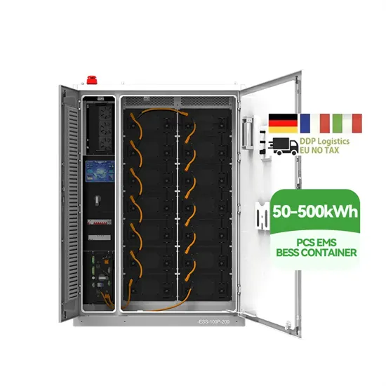
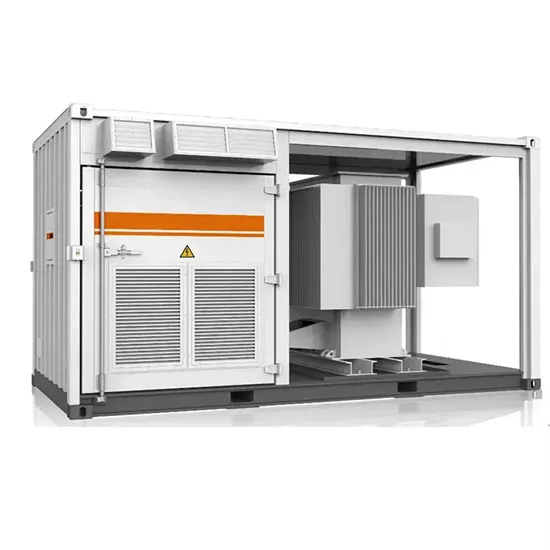
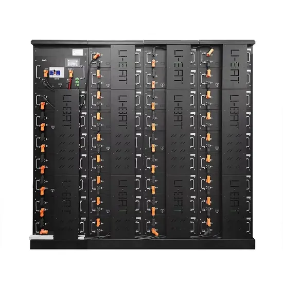
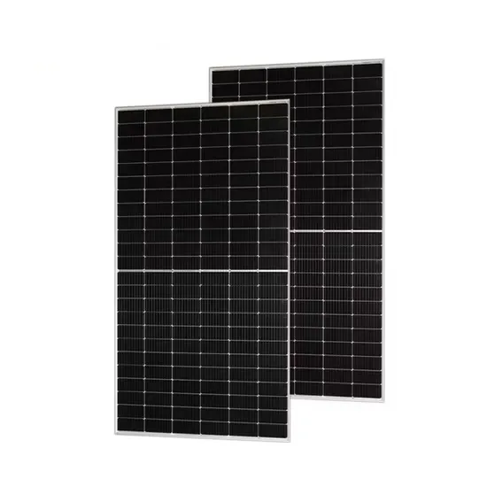
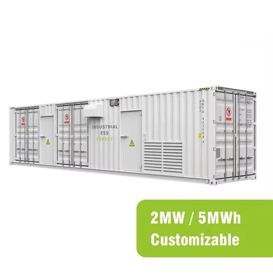
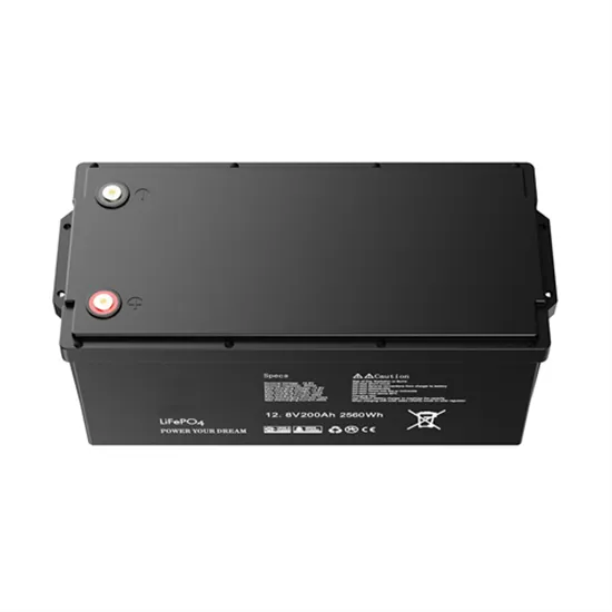
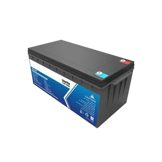
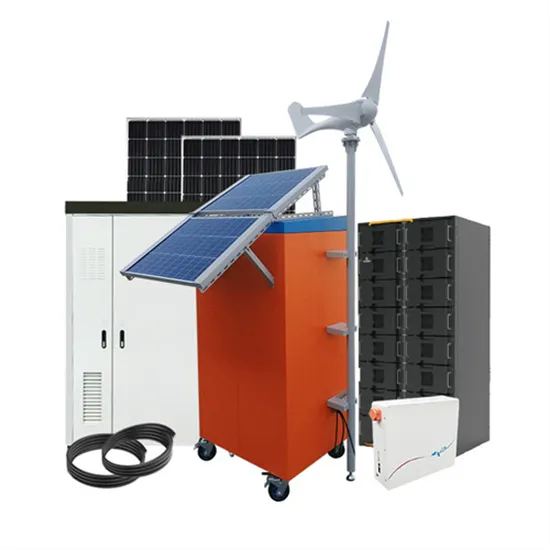
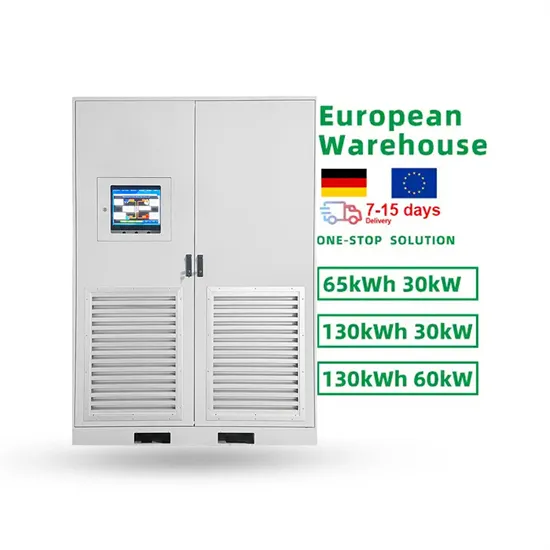
The global commercial and industrial solar energy storage battery market is experiencing unprecedented growth, with demand increasing by over 400% in the past three years. Large-scale battery storage solutions now account for approximately 45% of all new commercial solar installations worldwide. North America leads with 42% market share, driven by corporate sustainability goals and federal investment tax credits that reduce total system costs by 30-35%. Europe follows with 35% market share, where standardized industrial storage designs have cut installation timelines by 60% compared to custom solutions. Asia-Pacific represents the fastest-growing region at 50% CAGR, with manufacturing innovations reducing system prices by 20% annually. Emerging markets are adopting commercial storage for peak shaving and energy cost reduction, with typical payback periods of 3-6 years. Modern industrial installations now feature integrated systems with 50kWh to multi-megawatt capacity at costs below $500/kWh for complete energy solutions.
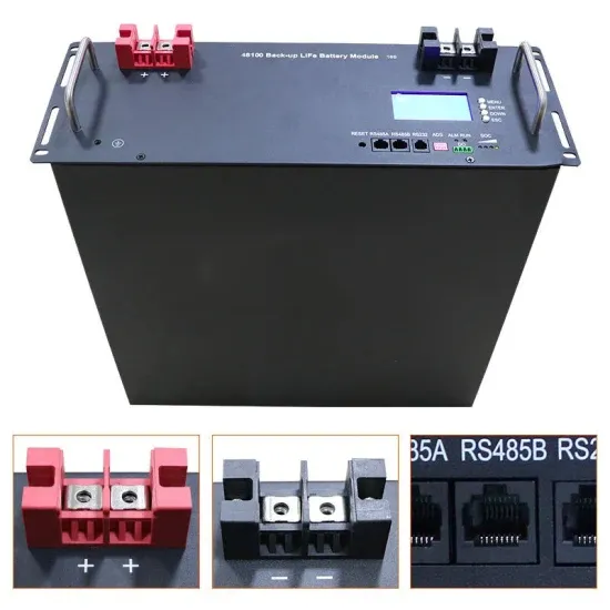
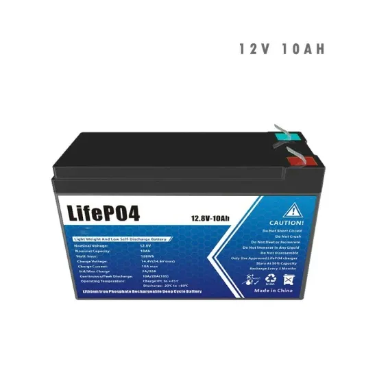
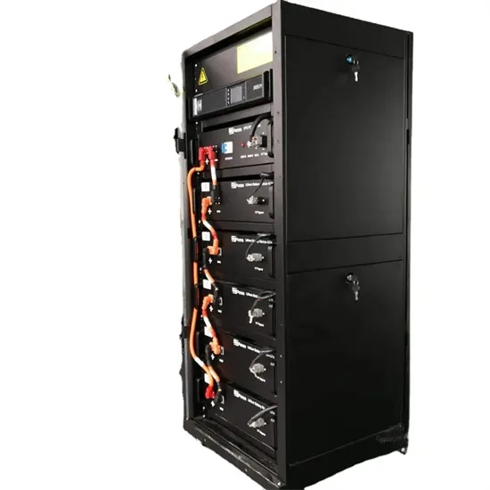
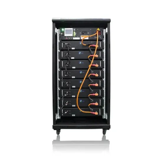
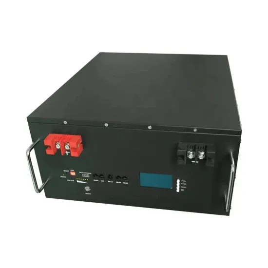
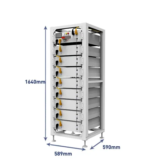
Technological advancements are dramatically improving solar energy storage battery performance while reducing costs for commercial applications. Next-generation battery management systems maintain optimal performance with 50% less energy loss, extending battery lifespan to 20+ years. Standardized plug-and-play designs have reduced installation costs from $1,000/kW to $550/kW since 2022. Smart integration features now allow industrial systems to operate as virtual power plants, increasing business savings by 40% through time-of-use optimization and grid services. Safety innovations including multi-stage protection and thermal management systems have reduced insurance premiums by 30% for commercial storage installations. New modular designs enable capacity expansion through simple battery additions at just $450/kWh for incremental storage. These innovations have improved ROI significantly, with commercial projects typically achieving payback in 4-7 years depending on local electricity rates and incentive programs. Recent pricing trends show standard industrial systems (50-100kWh) starting at $25,000 and premium systems (200-500kWh) from $100,000, with flexible financing options available for businesses.