 A single-phase full bridge inverter is a switching device that generates a square wave AC voltage in the output on the application of DC voltage in the input by adjusting the switch ON and OFF.What is the circuit model of single phase full bridge inverter?The circuit model of single phase full bridge inverter is same as illustrated in Fig. 27.38 (a). The load voltage and current waveforms for single phase full bridge inverter will be same as that shown in Fig. 27.38 (b) – (f), but the components conducting period will be different.
What is a full bridge inverter?Full bridge inverter is a topology of H-bridge inverter used for converting DC power into AC power. The components required for conversion are two times more than that used in single phase Half bridge inverters. The circuit of a full bridge inverter consists of 4 diodes and 4 controlled switches as shown below.
How does a single-phase full bridge inverter work?Positive input voltage will appear across the load by the operation of T1 and T2 for a half time period. The polarity of voltage across load will be changed for the other half period by operating T3 and T4. This article is about the working operation and waveform of a single-phase full bridge inverter for R load, RL load and RLC load.
How a single phase inverter works?Basic model to understand how actually single phase inverter works! Input is through Dc voltage source. Output can be seen at the load through multimeter. When Gto1 & Gto3 conducts load voltage is equal to dc voltage source. When Gto2 & Gto4 conducts load voltage is equal to negarive of dc voltage source. Saurabh Kabdal (2025).
What is a full bridge inverter (R-L-C load)?Construction and Working of Single Phase Full Bridge Inverter (R-L-C Load) What is a Full Bridge Inverter ? What is a Full Bridge Inverter ? Full bridge inverter is a topology of H-bridge inverter used for converting DC power into AC power.
What is a single phase bridge DC-AC inverter?A single phase bridge DC-AC inverter is shown in Figure below. The analysis of the single phase DC-AC inverters is done taking into account following assumptions and conventions. 1) The current entering node a in Figure 8 is considered to be positive. 2) The switches S1, S2, S3 and S4 are unidirectional, i.e. they conduct current in one directi
A single-phase full bridge inverter is a switching device that generates a square wave AC voltage in the output on the application of DC voltage in the input by adjusting the switch ON and OFF.What is the circuit model of single phase full bridge inverter?The circuit model of single phase full bridge inverter is same as illustrated in Fig. 27.38 (a). The load voltage and current waveforms for single phase full bridge inverter will be same as that shown in Fig. 27.38 (b) – (f), but the components conducting period will be different.
What is a full bridge inverter?Full bridge inverter is a topology of H-bridge inverter used for converting DC power into AC power. The components required for conversion are two times more than that used in single phase Half bridge inverters. The circuit of a full bridge inverter consists of 4 diodes and 4 controlled switches as shown below.
How does a single-phase full bridge inverter work?Positive input voltage will appear across the load by the operation of T1 and T2 for a half time period. The polarity of voltage across load will be changed for the other half period by operating T3 and T4. This article is about the working operation and waveform of a single-phase full bridge inverter for R load, RL load and RLC load.
How a single phase inverter works?Basic model to understand how actually single phase inverter works! Input is through Dc voltage source. Output can be seen at the load through multimeter. When Gto1 & Gto3 conducts load voltage is equal to dc voltage source. When Gto2 & Gto4 conducts load voltage is equal to negarive of dc voltage source. Saurabh Kabdal (2025).
What is a full bridge inverter (R-L-C load)?Construction and Working of Single Phase Full Bridge Inverter (R-L-C Load) What is a Full Bridge Inverter ? What is a Full Bridge Inverter ? Full bridge inverter is a topology of H-bridge inverter used for converting DC power into AC power.
What is a single phase bridge DC-AC inverter?A single phase bridge DC-AC inverter is shown in Figure below. The analysis of the single phase DC-AC inverters is done taking into account following assumptions and conventions. 1) The current entering node a in Figure 8 is considered to be positive. 2) The switches S1, S2, S3 and S4 are unidirectional, i.e. they conduct current in one directi

Nov 1, 2016 · It is observed the output current and output voltage of full bridge inverter is twice and generates less total harmonic distortion as compared to
Mar 13, 2024 · Single phase voltage source inverters: The inverter is a power electronic converter that converts direct power to alternating power. By using this inverter device, we can convert
Feb 15, 2023 · The single-phase full-bridge inverter is an electronic device used to convert direct current (DC) to alternating current (AC)
Jul 30, 2012 · Basic model to understand how actually single phase inverter works! Input is through Dc voltage source. Output can be seen at the load through multimeter. When Gto1 &
Feb 15, 2020 · DC AC Converter (PE 1ph VSI 3.sqproj) Question: A single-phase full-bridge voltage source inverter is fed from a DC source such that the fundamental RMS output voltage
Mar 12, 2024 · This article will analyze the functioning of the single-phase full-bridge inverter, an electronic apparatus employed for the conversion of direct
Jul 10, 2021 · The waveform of the single phase bridge inverter with resistive load is shown in the following Fig. 2. Fig. 2: Voltage and current waveforms with
Oct 30, 2023 · Here single phase inverter used is the full-bridge or h-bridge inverter. The required components to make this circuit are; Arduino Uno, 4093
Jun 16, 2020 · II. SINGLE PHASE VOLTAGE SOURCE INVERTER Voltage Source Inverters are used to transfer real power from a DC power source to an AC load. Usually, the DC source
May 11, 2022 · Voltage Source Inverter Reference Design Description This reference design implements single-phase inverter (DC/AC) control using a C2000TM microcontroller (MCU).
Single Phase Half Bridge Voltage Source Inverter It consists of 1 DC voltage source, 4 transistors S1, S2, S3, S4, and 4 anti-parallel diodes D1, D2, D3, D4
The load voltage and current waveforms for single phase full bridge inverter will be same as that shown in Fig. 27.38 (b) – (f), but the components conducting
The single-phase full-bridge voltage source inverter (VSI), shown in figure, has an output frequency of 50 H z. It uses unipolar pulse width modulation with switching frequency of 50 k H
Home Power Electronics Inverter Single Phase Full Bridge Inverter Single Phase Full Bridge Inverter A single-phase full bridge inverter is designed to convert DC input into a two-level AC
Feb 15, 2020 · Question: A single phase full bridge voltage source inverter (VSI) is shown in Fig 1. It is controlled by using pulse width modulation (PWM) technique with one pulse per half cycle.
A single-phase square wave type voltage source inverter produces square shaped output voltage for a single-phase load. Such inverters have very
Full-bridge inverters offer improved performance and are often used in many single-phase inverter applications, including motor drives, solar inverters, and UPS systems, despite having a larger
Feb 19, 2024 · The output voltage of a single-phase full bridge voltage source inverter is controlled by unipolar PWM with one pulse per half cycle. For the fundamental rms component
Jul 10, 2021 · Single Phase Inverter is an electrical circuit, converts a fixed voltage DC to a fixed (or variable) single phase AC voltage with variable frequency. A single Phase Inverter can be

Currently, there are two types of voltage inverters on the market: the first is a full-bridge voltage source inverter, which consists of four switches, IGBTs, or
Dec 22, 2023 · link converter. Inverters can be broadly classified into two types, voltage source and current source inverters. A voltage–fed inverter (VFI) or more generally a voltage–source
May 15, 2025 · Example: The full-bridge inverter has a switching sequence that produces a square wave voltage across a series RL load. The switching frequency is 60 Hz, Vs=100 V,

Jul 30, 2012 · Single Phase Full Bridge Inverter Input is through Dc voltage source. Output can be seen at the load through multimeter. When Gto1 & Gto3 conducts load voltage is equal to dc
A single-phase bridge inverter is defined as a type of DC–AC inverter that converts direct current (DC) into alternating current (AC) using a bridge configuration, typically employed in
Jul 12, 2021 · Single Phase Full Bridge Inverter is basically a voltage source inverter and it is a topology of H-bridge inverter used for converting DC power
Nov 16, 2016 · This research work is organized in two sections. Performance comparison of single phase half bridge inverter and single phase full bridge inverter is done in the first section. It is
Single Phase Full Bridge Inverter: The main drawback of half-bridge inverter is that it requires 3-wire dc supply. This difficulty can, however, be overcome by
The adequacy of output voltage and output current of single-phase full-bridge inverter is multiplied when contrasted with single-stage half-bridge inverter. Amid inverter operation, two thyristors
Feb 19, 2024 · A single-phase full-bridge voltage source inverter (VSI) is fed from a 300 V battery. A pulse of 120 o duration is used to trigger the appropriate
Mar 20, 2022 · In this article, let us learn about the full-bridge inverter with circuit diagrams and waveforms. Full Bridge Inverter With R Load : The below figure
Dec 26, 2020 · In this article, we will discuss about the basics of a Single Phase Full Bridge Voltage Source Inverter such as its working using diagram, waveforms for various loads (R, L,
Nov 16, 2016 · This research work is organized in two sections. Performance comparison of single phase half bridge inverter and single phase full bridge inverter is done in th
Aug 25, 2017 · 3 Single Phase Inverter Design A typical inverter comprises of a full bridge that is constructed with four switches which can be modulated using Pulse Width Modulation (PWM),
Jul 14, 2021 · Single Phase Full Bridge Inverter is basically a voltage source inverter and it is a topology of H-bridge inverter used for converting DC power
Aug 6, 2020 · This article outlines the basic operating or working principle of a Single Phase Half Bridge Inverter with the help of circuit diagram.
The circuit model of single phase full bridge inverter is same as illustrated in Fig. 27.38 (a). The load voltage and current waveforms for single phase full bridge inverter will be same as that shown in Fig. 27.38 (b) – (f), but the components conducting period will be different.
Full bridge inverter is a topology of H-bridge inverter used for converting DC power into AC power. The components required for conversion are two times more than that used in single phase Half bridge inverters. The circuit of a full bridge inverter consists of 4 diodes and 4 controlled switches as shown below.
Positive input voltage will appear across the load by the operation of T1 and T2 for a half time period. The polarity of voltage across load will be changed for the other half period by operating T3 and T4. This article is about the working operation and waveform of a single-phase full bridge inverter for R load, RL load and RLC load.
Basic model to understand how actually single phase inverter works! Input is through Dc voltage source. Output can be seen at the load through multimeter. When Gto1 & Gto3 conducts load voltage is equal to dc voltage source. When Gto2 & Gto4 conducts load voltage is equal to negarive of dc voltage source. Saurabh Kabdal (2025).
Construction and Working of Single Phase Full Bridge Inverter (R-L-C Load) What is a Full Bridge Inverter ? What is a Full Bridge Inverter ? Full bridge inverter is a topology of H-bridge inverter used for converting DC power into AC power.
A single phase bridge DC-AC inverter is shown in Figure below. The analysis of the single phase DC-AC inverters is done taking into account following assumptions and conventions. 1) The current entering node a in Figure 8 is considered to be positive. 2) The switches S1, S2, S3 and S4 are unidirectional, i.e. they conduct current in one direction.
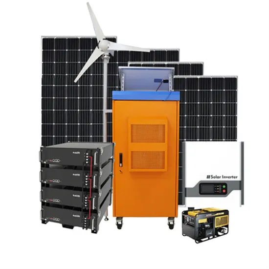
The global commercial and industrial solar energy storage battery market is experiencing unprecedented growth, with demand increasing by over 400% in the past three years. Large-scale battery storage solutions now account for approximately 45% of all new commercial solar installations worldwide. North America leads with 42% market share, driven by corporate sustainability goals and federal investment tax credits that reduce total system costs by 30-35%. Europe follows with 35% market share, where standardized industrial storage designs have cut installation timelines by 60% compared to custom solutions. Asia-Pacific represents the fastest-growing region at 50% CAGR, with manufacturing innovations reducing system prices by 20% annually. Emerging markets are adopting commercial storage for peak shaving and energy cost reduction, with typical payback periods of 3-6 years. Modern industrial installations now feature integrated systems with 50kWh to multi-megawatt capacity at costs below $500/kWh for complete energy solutions.
Technological advancements are dramatically improving solar energy storage battery performance while reducing costs for commercial applications. Next-generation battery management systems maintain optimal performance with 50% less energy loss, extending battery lifespan to 20+ years. Standardized plug-and-play designs have reduced installation costs from $1,000/kW to $550/kW since 2022. Smart integration features now allow industrial systems to operate as virtual power plants, increasing business savings by 40% through time-of-use optimization and grid services. Safety innovations including multi-stage protection and thermal management systems have reduced insurance premiums by 30% for commercial storage installations. New modular designs enable capacity expansion through simple battery additions at just $450/kWh for incremental storage. These innovations have improved ROI significantly, with commercial projects typically achieving payback in 4-7 years depending on local electricity rates and incentive programs. Recent pricing trends show standard industrial systems (50-100kWh) starting at $25,000 and premium systems (200-500kWh) from $100,000, with flexible financing options available for businesses.