 What is tl494 power supply control circuit?The TL494 is a fixed frequency, pulse width modulation control circuit designed primarily for SWITCHMODE power supply control. 1. Complete Pulse Width Modulation Control Circuitry 2. On–Chip Oscillator with Master or Slave Operation 3. On–Chip Error Amplifiers 4. On–Chip 5.0 V Reference 5. Adjustable Deadtime Control 6.
What does tl494 mean?The TL494 is a fixed frequency, pulse width modulation control circuit designed primarily for switch mode power supply control. MAXIMUM RATINGS (Full operating ambient temperature range applies, unless otherwise noted.) Stresses exceeding those listed in the Maximum Ratings table may damage the device.
What is a tl494 overvoltage protection circuit?Overvoltage-Protection Circuit The following design example uses the TL494 to create a 5-V/10-A power supply. This design is based on the following parameters: The 32-V dc power source for this supply uses a 120-V input, 24-V output transformer rated at 75 VA.
What are the components of tl494?The TL494 device contains two error amplifiers, an on-chip adjustable oscillator, a dead-time control (DTC) comparator, a pulse-steering control flip-flop, a 5-V, 5%-precision regulator, and output-control circuits. The error amplifiers exhibit a common-mode voltage range from –0.3 V to VCC – 2 V.
What voltage is tl494?Reference Voltage vs Input Voltage The TL494 is designed to operate from an input voltage supply range between 7 V and 40 V. This input supply should be well regulated. If the input supply is located more than a few inches from the device, additional bulk capacitance may be required in addition to the ceramic bypass capacitors.
Does the tl494 use a noninverting amplifier?The design of the TL494 employs both amplifiers in a noninverting configuration. Figure 23 shows the proper bias circuits for negative and positive output voltages. The gain control circuits, shown in Figure 11, can be integrated into the bias circuits. Figure 23. Error-Amplifier-Bias Configurati
What is tl494 power supply control circuit?The TL494 is a fixed frequency, pulse width modulation control circuit designed primarily for SWITCHMODE power supply control. 1. Complete Pulse Width Modulation Control Circuitry 2. On–Chip Oscillator with Master or Slave Operation 3. On–Chip Error Amplifiers 4. On–Chip 5.0 V Reference 5. Adjustable Deadtime Control 6.
What does tl494 mean?The TL494 is a fixed frequency, pulse width modulation control circuit designed primarily for switch mode power supply control. MAXIMUM RATINGS (Full operating ambient temperature range applies, unless otherwise noted.) Stresses exceeding those listed in the Maximum Ratings table may damage the device.
What is a tl494 overvoltage protection circuit?Overvoltage-Protection Circuit The following design example uses the TL494 to create a 5-V/10-A power supply. This design is based on the following parameters: The 32-V dc power source for this supply uses a 120-V input, 24-V output transformer rated at 75 VA.
What are the components of tl494?The TL494 device contains two error amplifiers, an on-chip adjustable oscillator, a dead-time control (DTC) comparator, a pulse-steering control flip-flop, a 5-V, 5%-precision regulator, and output-control circuits. The error amplifiers exhibit a common-mode voltage range from –0.3 V to VCC – 2 V.
What voltage is tl494?Reference Voltage vs Input Voltage The TL494 is designed to operate from an input voltage supply range between 7 V and 40 V. This input supply should be well regulated. If the input supply is located more than a few inches from the device, additional bulk capacitance may be required in addition to the ceramic bypass capacitors.
Does the tl494 use a noninverting amplifier?The design of the TL494 employs both amplifiers in a noninverting configuration. Figure 23 shows the proper bias circuits for negative and positive output voltages. The gain control circuits, shown in Figure 11, can be integrated into the bias circuits. Figure 23. Error-Amplifier-Bias Configurati
Aug 8, 2024 · Supercharge inverter safety with top protection tips. Learn to shield against surges, overcurrent, and temperature extremes for lasting performance!
Aug 25, 2013 · I have made an inverter using tl494 and sg3524 chips but there is no overload protection circuit.what changes should I make for the protection circuit.
Sep 29, 2021 · Short-circuit protection is provided to protect the internal reference and preregulator; 10 mA of load current is available for additional bias circuits. The reference is
Mar 31, 2023 · In addition to the function that regulates speed, the inverter also encompasses a safeguard function for the motor. The inverter is a controlling

Applicable to SH15-20-25T seriesThis manual is intended for professional technicians who are responsible for installation, operation, maintenance and troubleshooting of inverters, and users
Sep 20, 2023 · DESCRIPTION The TL494 incorporate on a single monolithic chip all the functions required in the construction of a pulse-width-modulation control, these devices offer the
Dec 3, 2014 · The document discusses removing the inverter protection circuit to repair LCD displays when lamps are faulty. It lists several chip models and the pins that could cause short
Sep 29, 2019 · 13. Leak current monitoring and protection: The solar grid tie inverter has the perfect leak current monitoring function. In the operation
Dec 14, 2023 · Solar inverter is one of the essential core components in solar power generation applications. In addition to affecting the power generation of
This article provides information about protection of your circuits from under and overvolatge by using protection circuit diagram with opamps and timers.
Undervoltage Protection Undervoltage protection prevents the inverter from operating under low voltage conditions. If the DC input voltage drops below the minimum required level, the
Feb 3, 2025 · To completely turn off the IC, VCC voltage needs to be below 3.5V. Between 6.9V and 3.5V the IC working is not certain so should be avoided. DTC voltage rating is same as
Nov 4, 2022 · 图片来源于网络 今天是 TL494 开关电源芯片, 主要是以下几个方面: 1、什么是 TL494芯片? 2、TL494 引脚图及功能 3、TL494 CAD 模型 4
TL494 Current-Mode PWM Controller IC The TL494 is a flexible pulse-width modulation (PWM) controller used in automotive, industrial, and consumer
If you log in to the app as Special User, you can set grid parameters, protection parameters, feature parameters, and power adjustment parameters for the SUN2000.

2 days ago · Under Voltage wave form [wp_ad_camp_1] Reason Under voltage protection: i.e The output from the generator''s LAVT potential transformer will
Nov 5, 2018 · description The TL494 incorporates all the functions required in the construction of a pulse-width-modulation (PWM) control circuit on a single chip. Designed primarily for power
TL494C Product details 1 Features • Complete PWM Power-Control Circuitry • Uncommitted Outputs for 200-mA Sink or Source Current • Output Control
Apr 21, 2025 · Modern inverters are equipped with built-in protection systems to keep your equipment safe, stable, and efficient. These features prevent
The TL494 PWM Controller contains two error amplifiers, an on-chip adjustable oscillator, a dead-time control (DTC) comparator, a pulse-steering control flip-flop, a 5-V, 5%-precision regulator,

10 hours ago · Clear answers on Portable inverters: FRT protection or fast‑acting short‑circuit protection? Get inverter protection requirements, timing, and field‑tested settings.
Presentation Undervoltage protection (ANSI 27) constantly monitors the system voltage. If the voltage level of an installation goes out of its acceptable limits,
TI-Produkt TL494 ist ein (e) 40-V-, 0,2-A-, 300-kHz-PWM-Controller. Parameter-, Bestell- und Qualitätsinformationen finden
The TL494 is a fixed frequency, pulse width modulation control circuit designed primarily for SWITCHMODE power supply control. 1. Complete Pulse Width
Jul 1, 2024 · TL494 inverter Here''s a classic inverter circuit built around the IC TL494. In this example the output is configured to work in the push-pull
Feb 6, 2022 · The TL494 device contains two error amplifiers, an on-chip adjustable oscillator, a dead-time control (DTC) comparator, a pulse-steering control flip-flop, a 5-V, 5%-precision
Dec 21, 2023 · In this project I will be building a simple modified square wave PWM inverter circuit by using the popular TL494 IC and explain the pros and
Apr 1, 2023 · Short-circuit protection is provided to protect the internal reference and preregulator; 10 mA of load current is available for additional bias circuits. The reference is internally
TL494 pulse width modulation control IC Pinout, Working Examples, Features, datasheet and Applications and How to design buck converter circuit
The TL494 is a fixed frequency, pulse width modulation control circuit designed primarily for SWITCHMODE power supply control. 1. Complete Pulse Width Modulation Control Circuitry 2. On–Chip Oscillator with Master or Slave Operation 3. On–Chip Error Amplifiers 4. On–Chip 5.0 V Reference 5. Adjustable Deadtime Control 6.
The TL494 is a fixed frequency, pulse width modulation control circuit designed primarily for switch mode power supply control. MAXIMUM RATINGS (Full operating ambient temperature range applies, unless otherwise noted.) Stresses exceeding those listed in the Maximum Ratings table may damage the device.
Overvoltage-Protection Circuit The following design example uses the TL494 to create a 5-V/10-A power supply. This design is based on the following parameters: The 32-V dc power source for this supply uses a 120-V input, 24-V output transformer rated at 75 VA.
The TL494 device contains two error amplifiers, an on-chip adjustable oscillator, a dead-time control (DTC) comparator, a pulse-steering control flip-flop, a 5-V, 5%-precision regulator, and output-control circuits. The error amplifiers exhibit a common-mode voltage range from –0.3 V to VCC – 2 V.
Reference Voltage vs Input Voltage The TL494 is designed to operate from an input voltage supply range between 7 V and 40 V. This input supply should be well regulated. If the input supply is located more than a few inches from the device, additional bulk capacitance may be required in addition to the ceramic bypass capacitors.
The design of the TL494 employs both amplifiers in a noninverting configuration. Figure 23 shows the proper bias circuits for negative and positive output voltages. The gain control circuits, shown in Figure 11, can be integrated into the bias circuits. Figure 23. Error-Amplifier-Bias Configurations
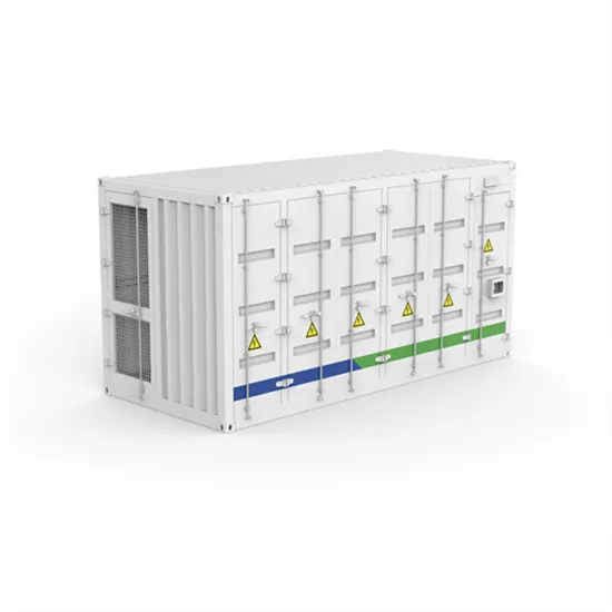
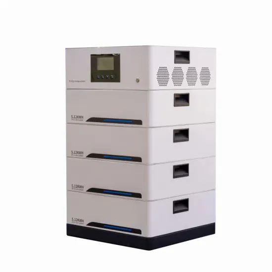
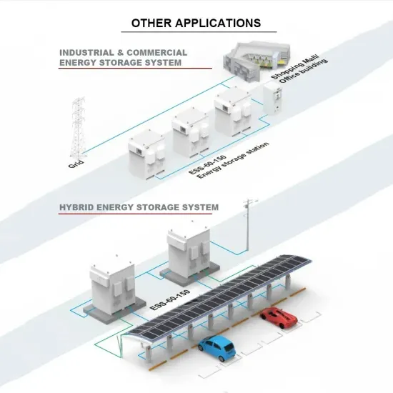
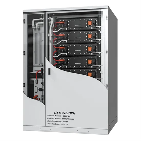
The global commercial and industrial solar energy storage battery market is experiencing unprecedented growth, with demand increasing by over 400% in the past three years. Large-scale battery storage solutions now account for approximately 45% of all new commercial solar installations worldwide. North America leads with 42% market share, driven by corporate sustainability goals and federal investment tax credits that reduce total system costs by 30-35%. Europe follows with 35% market share, where standardized industrial storage designs have cut installation timelines by 60% compared to custom solutions. Asia-Pacific represents the fastest-growing region at 50% CAGR, with manufacturing innovations reducing system prices by 20% annually. Emerging markets are adopting commercial storage for peak shaving and energy cost reduction, with typical payback periods of 3-6 years. Modern industrial installations now feature integrated systems with 50kWh to multi-megawatt capacity at costs below $500/kWh for complete energy solutions.
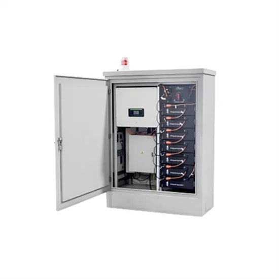
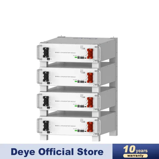
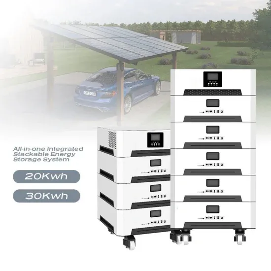
Technological advancements are dramatically improving solar energy storage battery performance while reducing costs for commercial applications. Next-generation battery management systems maintain optimal performance with 50% less energy loss, extending battery lifespan to 20+ years. Standardized plug-and-play designs have reduced installation costs from $1,000/kW to $550/kW since 2022. Smart integration features now allow industrial systems to operate as virtual power plants, increasing business savings by 40% through time-of-use optimization and grid services. Safety innovations including multi-stage protection and thermal management systems have reduced insurance premiums by 30% for commercial storage installations. New modular designs enable capacity expansion through simple battery additions at just $450/kWh for incremental storage. These innovations have improved ROI significantly, with commercial projects typically achieving payback in 4-7 years depending on local electricity rates and incentive programs. Recent pricing trends show standard industrial systems (50-100kWh) starting at $25,000 and premium systems (200-500kWh) from $100,000, with flexible financing options available for businesses.