Voltage ripple analysis based on DC-link current harmonics for Voltage
Jun 20, 2019 · The voltage ripple is the predominant dc-link capacitor design parameter in automotive traction voltage source inverters. Therefore, the reduction of the voltag
230-V/250-W, Hi-η Sensorless Brushless DC Motor Drive
May 12, 2016 · TI Designs The TIDA-00472 is a discrete IGBT-based three-phase inverter for driving brushless DC (BLDC) motors rated up to 250 W using the sensorless, trapezoidal
Reducing the DC-Link Voltage Ripple by Optimized Pulse
Nov 7, 2024 · The DC-link capacitor represents a critical component in electric vehicle traction inverters, given that it constitutes the largest single volume within a traction inverter. The DC
Understanding and Mitigating Inverter Feedback Ripple Voltage
Summary: Inverter feedback ripple voltage is a critical challenge in renewable energy systems. This article explores its causes, impacts on solar installations, and proven solutions. Learn
The strategy of second harmonic voltage match suppression
Apr 1, 2022 · A second band passing filter (BPF) feedback control loop is used to feedback the second harmonic ripple voltage in DC link into the statable modulation index. This strategy can
DC-Link Ripple Reduction for Parallel Inverter
Mar 22, 2023 · This paper proposes an analytical formulation-based minimization of DC link current ripples for interleaved parallel inverter systems. Parallel
Dynamic response of the current feedback ripple
Dynamic response of the current feedback ripple reduction method for a 15W, 10VAr step change. (a) Input current ripple component without (K=0) and with
(PDF) Analysis of DC-Link Voltage Ripple in
Oct 1, 2018 · As the capacitance density of non-electrolytic capacitors are significantly lower than electrolytic capacitors, for a non-electrolytic capacitor
Analysis of DC-Link Voltage Ripple in Voltage Source
Dec 27, 2023 · The DC-link voltage ripple of a voltage source inverter using modulation methods of SPWM and SVPWM is analyzed in section II. The power loss calculation of DC-link
What should be the maximum allowable input ripple voltage
I need to design a 3 phase pwm inverter and I am not able to determine the input dc link capacitor because I don''t know the standard criterion of allowable ripple voltage.
Fast and robust DC link voltage control of single-phase grid
Dec 1, 2023 · When sensed and fed back to DC link regulation loop, DC link voltage ripple component distorts the grid-current reference, increasing corresponding THD value [10].
What is Ripple Voltage in Victron Inverters?
Jan 14, 2024 · Acceptable Ripple Voltage Levels: Normal: In a perfectly wired installation with the inverter under full load, a ripple voltage of + / – 0.6 to 0.8 volts is considered normal. Pre
Low-frequency current ripple reduction in front-end boost
Nov 7, 2012 · The low-frequency current ripple that always appears at the input of the single-phase DC/AC inverters decreases the lifetime of DC voltage sources, such as fuel cells and
Time-Offset Injection Method for Neutral-Point AC Ripple Voltage
Jun 1, 2015 · The purpose of neutral-point voltage balancing algorithms in the three-level neutral-point clamped (3L-NPC) topology is to eliminate the voltage unbalance of top- and bottom-side
Harmonic Distortion Caused by Single-Phase
May 30, 2018 · The inverter is modeled as a time-varying system by considering the DC-link voltage ripple. A closed-form solution is derived to calculate the

Research on DC-Link Ripple Voltage Compensation for
Aug 9, 2024 · Photovoltaic systems are generating interest as efficient renewable energy sources owing to the lowering of the price and cost of power generation with the progress of research
Outer voltage control loop and inner current
Download scientific diagram | Outer voltage control loop and inner current control loop for the left hand side boost converter leg. from publication: An Input
Evaluation of DC voltage ripple in three-phase PWM voltage source inverters
Jun 21, 2017 · Determination of dc-link voltage switching ripple in three-phase PWM voltage source inverters (VSI) is important for the selection and design of the dc-link capacitor. In this
[PDF] A Compound Control Strategy for Improving the
Oct 18, 2019 · Simulation and experimental results indicate that the compound control strategy effectively improves the static and dynamic characteristics of the DC-link voltage and reduces
Analysis of dc-Link Voltage Switching Ripple in Three
The three-phase voltage source inverter (VSI) is de facto standard in power conversion systems. To realize high power density systems, one of the items to be correctly addressed is the
Analysis of DC-Link Voltage Ripple in Voltage Source Inverters
Oct 23, 2018 · In this paper, the DC-link voltage ripple is analyzed for an inverter without electrolytic capacitor. As the capacitance density of non-electrolytic capacitors
Theoretical and Experimental Investigation of
Direct current (DC)-link voltage ripple analysis is essential for determining harmonic noise and for DC-link capacitor design and selection in single-phase
SVM strategy and analysis of a three-phase quasi-Z-source inverter
Aug 2, 2023 · Herein, we propose a novel three-phase quasi-Z-source inverter with a high voltage transmission ratio to address challenges such as high switching loss and sizeable magnetic
Feedforward Ripple Cancellation for a Full-Bridge
Jul 19, 2016 · Depending on the battery technology, this ripple could lead to ex- cessive, unacceptable peak currents, and even discon- tinous charging current. This paper presents a
Analysis and minimization of input ripple current in PWM inverters
Jun 1, 2006 · This paper presents the implementation of a technique to minimize the input ripple current in three-phase voltage-source pulse width modulated (PWM) inverters when supplying
Voltage Multiplier Cell-Based Quasi-Switched Boost Inverter
Feb 18, 2019 · A novel single-phase single-stage voltage multiplier cell-based quasi-switched boost inverter (VMC-qSBI) is proposed in this paper. By adding the voltage multiplier cell to
Maximum power extraction and DC-Bus voltage regulation
Nov 19, 2022 · This presumption results in the inverter''s dynamic impedance to be dependent on the variation of the DC-Bus voltage since the changed impedance is exactly proportional to the
Evaluation of Current Ripple Amplitude in Three-Phase
Nov 17, 2020 · Abstract — Determination of current ripple in three-phase PWM voltage source inverters (VSI) is important for both de-sign and control purposes, since this is the most
Research on DC-Link Ripple Voltage Compensation for
Oct 21, 2024 · The ripple voltage afects the inverter controller and generates harmonics in the out-put inverter current, thereby increasing the current distor-tion factor and degrading the overall
Analysis of DC-Link Current and Voltage Ripple: Three-Phase
Jan 5, 2019 · A complete analysis of dc-link voltage ripple for three-phase two-level inverters is presented in [4], considering both switching frequency and double fundamental frequency

Ripple Current Analysis of Three-level Inverter based on
Feb 18, 2016 · In this paper, with the three level voltage inverter using space vector pulse width modulation (SVPWM) as the study object, the ripple current of the inductor current in is analyzed.
Analysis of dc-Link Voltage Switching Ripple in Three
Aug 2, 2024 · Analytical results were validated both by simulations and comprehensive experimental tests. Keywords: voltage ripple; voltage source inverter; three-phase inverter; dc
Voltage ripple analysis of simplified active power
Oct 1, 2014 · As for the compensation of unbalanced load, a simplified active power quality compensator (SAPC) was discussed, which consists of a three-phase two-leg inverter and a
Evaluation of DC voltage Ripple in Three-Phase
PDF | On Apr 7, 2017, marija vujajic and others published Evaluation of DC voltage Ripple in Three-Phase PWM Voltage Source Inverters | Find, read and
Experimental result of DC-link voltage ripple in
Oct 10, 2023 · In this paper, the DC-link voltage ripple is analyzed for an inverter without electrolytic capacitor. As the capacitance density of non-electrolytic
6 FAQs about [Inverter feedback ripple voltage]
Can DC-link voltage ripple be analyzed for a non-electrolytic DC-link capacitor three-phase inverter?
To avoid these disadvantages, the DC-link voltage ripple must be fully analyzed for a non-electrolytic DC-link capacitor three-phase inverter. This paper presents the voltage ripple analysis of the voltage source inverter under the modulation methods of SPWM and SVPWM.
How is DC-link voltage ripple measured in a five-phase inverter?
In the case of a five-phase inverter supplying a five-phase R – L load, the dc-link voltage ripple across the dc-link capacitor was measured by Tektronix P5205A, 100 MHz, high voltage differential probe.
How voltage source inverter is rippled under modulation methods?
This paper presents the voltage ripple analysis of the voltage source inverter under the modulation methods of SPWM and SVPWM. The results show that the DC-link voltage ripple has special patterns which relate to switching frequency, modulation ratio, output current amplitude, load power factor, and reference voltage angle.
How DC-link current and voltage ripple affect inverter performance?
Abstract Inverter's performance and operating mode may be negatively affected by inverter input (dc-link) current and voltage ripple. It is a common experience that even theoretically balanced load...
What causes a voltage ripple on a DC-link capacitor?
For a conventional hard-switching three-phase voltage source converter, the DC-link capacitor should be big enough to mitigate the voltage ripple to a tolerable value. Generally, two reasons will cause the voltage ripple on the DC-link, one is the pulsating current at the switching frequency which will cause high frequency voltage ripple.
Is there a generalised approach to DC-link voltage switching ripple analysis?
Regarding the two-level multiphase VSIs, a generalised approach towards the dc-link voltage switching ripple analysis has been presented in Ref. . The guideline for designing a dc-link capacitor, based on the maximum (peak-to-peak) value of the dc-link voltage ripple, has been provided considering balanced loads.
Industry Information
- Somaliland Power Battery Energy Storage Company
- Managua Energy Storage Cabinet Sale Price Inquiry
- Energy storage batteries for factories
- Vietnam 20MW energy storage project
- Bishkek high capacity supercapacitor price
- UPS must use battery cabinet
- Cameroon BESS Uninterruptible Power Supply
- How much does a 6-watt solar panel set cost
- Ankara City Energy Storage Container Factory is in operation
- What are the wind power setting standards for communication base stations
- Spanish solar energy intelligent control system manufacturer
- Sri Lanka Power Emergency Energy Storage Manufacturer
- Dominica container energy storage supply
- Low voltage processing of communication base stations
- 500 watt solar panel
- Photovoltaic panel manufacturers for sale in Malawi
- Chromium flow battery stack
- Battery energy storage device structure frame
- The role of large capacitors in photovoltaic inverters
- Single-glass photovoltaic module panels in Mombasa Kenya
- China circuit breaker outside in Jamaica
- Photovoltaic panel installation manufacturer in Yamoussoukro
- Flow battery stack structure
Commercial & Industrial Solar Storage Market Growth
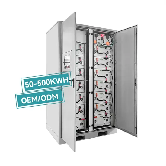
The global commercial and industrial solar energy storage battery market is experiencing unprecedented growth, with demand increasing by over 400% in the past three years. Large-scale battery storage solutions now account for approximately 45% of all new commercial solar installations worldwide. North America leads with 42% market share, driven by corporate sustainability goals and federal investment tax credits that reduce total system costs by 30-35%. Europe follows with 35% market share, where standardized industrial storage designs have cut installation timelines by 60% compared to custom solutions. Asia-Pacific represents the fastest-growing region at 50% CAGR, with manufacturing innovations reducing system prices by 20% annually. Emerging markets are adopting commercial storage for peak shaving and energy cost reduction, with typical payback periods of 3-6 years. Modern industrial installations now feature integrated systems with 50kWh to multi-megawatt capacity at costs below $500/kWh for complete energy solutions.
Solar Battery Innovations & Industrial Cost Benefits
Technological advancements are dramatically improving solar energy storage battery performance while reducing costs for commercial applications. Next-generation battery management systems maintain optimal performance with 50% less energy loss, extending battery lifespan to 20+ years. Standardized plug-and-play designs have reduced installation costs from $1,000/kW to $550/kW since 2022. Smart integration features now allow industrial systems to operate as virtual power plants, increasing business savings by 40% through time-of-use optimization and grid services. Safety innovations including multi-stage protection and thermal management systems have reduced insurance premiums by 30% for commercial storage installations. New modular designs enable capacity expansion through simple battery additions at just $450/kWh for incremental storage. These innovations have improved ROI significantly, with commercial projects typically achieving payback in 4-7 years depending on local electricity rates and incentive programs. Recent pricing trends show standard industrial systems (50-100kWh) starting at $25,000 and premium systems (200-500kWh) from $100,000, with flexible financing options available for businesses.

