 What is a bipolar PWM single-phase inverter?A bipolar PWM single-phase inverter is a type of power electronic device used to convert DC (direct current) power into AC (alternating current) power with a single-phase output.
What is pulse width modulation (PWM) for inverters?The concept of Pulse Width Modulation (PWM) for inverters is described with analyses extended to different kinds of PWM strategies. Finally the presented. battery or rectifier provides the dc supply to the inverter. The inverter is used to voltage. AC loads may require constant or adjustable voltage at their input terminals.
What are the different types of PWM inverters?PWM inverters can be of single phase as well as three phase types. The power circuit of Single Phase Unipolar inverter consists of four bidirectional IGBT arranged in bridge form. The circuit diagram of the power circuit is shown in Figure below. The circuit diagram consists of four distinct IGBTs such that they are connected as the bridge circuit.
What is PWM inverter?PWM Inverter uses PWM (Pulse Width Modulation) technique to control the output voltage of the inverter, this is done to fulfill the AC load requirements. In PWM inverter the controlled output is obtained by adjusting the ON and OFF period of the inverter components.
What is a single phase square wave inverter?Due to their mode of operation, losses in these semiconductor devices are very small and consequently they have a higher efficiency with much more power handling capability. There are three basic configurations of single phase square wave inverters are centre – tapped load, centre -tapped supply and bridge configuration.
Can Arduino be used to implement pulse width modulation on a single-phase inverter?This project has the aim to use Arduino board to ease the Pulse Width Modulation (PWM) implementation on a single-phase inverter, substituting analogical circuitry. To achieve those aims, a first complete theoretical analysis will be made, including the study of the different conventional PWM techniqu
What is a bipolar PWM single-phase inverter?A bipolar PWM single-phase inverter is a type of power electronic device used to convert DC (direct current) power into AC (alternating current) power with a single-phase output.
What is pulse width modulation (PWM) for inverters?The concept of Pulse Width Modulation (PWM) for inverters is described with analyses extended to different kinds of PWM strategies. Finally the presented. battery or rectifier provides the dc supply to the inverter. The inverter is used to voltage. AC loads may require constant or adjustable voltage at their input terminals.
What are the different types of PWM inverters?PWM inverters can be of single phase as well as three phase types. The power circuit of Single Phase Unipolar inverter consists of four bidirectional IGBT arranged in bridge form. The circuit diagram of the power circuit is shown in Figure below. The circuit diagram consists of four distinct IGBTs such that they are connected as the bridge circuit.
What is PWM inverter?PWM Inverter uses PWM (Pulse Width Modulation) technique to control the output voltage of the inverter, this is done to fulfill the AC load requirements. In PWM inverter the controlled output is obtained by adjusting the ON and OFF period of the inverter components.
What is a single phase square wave inverter?Due to their mode of operation, losses in these semiconductor devices are very small and consequently they have a higher efficiency with much more power handling capability. There are three basic configurations of single phase square wave inverters are centre – tapped load, centre -tapped supply and bridge configuration.
Can Arduino be used to implement pulse width modulation on a single-phase inverter?This project has the aim to use Arduino board to ease the Pulse Width Modulation (PWM) implementation on a single-phase inverter, substituting analogical circuitry. To achieve those aims, a first complete theoretical analysis will be made, including the study of the different conventional PWM techniqu
Apr 7, 2021 · The net 3 phase PWM inverter comprises of 3 single-phase inverters having control voltage comprising of the sine wave having one
CHAPTER 2 SINGLE PHASE PULSE WIDTH MODULATED INVERTERS 2.1 Introduction The dc-ac converter, also known as the inverter, converts dc
Jul 28, 2025 · Ballarpur Institute of Technology, Ballarpur, India Abstract: An inverter is device that changes the dc voltage into ac voltage thus inverter plays an important role in modern
Explore single-phase pulse width modulated inverters, voltage control, and SPWM techniques. Ideal for electrical engineering students.
Sep 17, 2020 · The complete design is modeled in Proteus software and its output is verified practically. Keywords— Single-phase inverter, PWM, Arduino; Proteus simulations I.
Jun 20, 2020 · The document discusses a voltage source inverter project. It begins by acknowledging those who provided guidance and support for the
Oct 27, 2024 · A bipolar PWM single-phase inverter is a type of power electronic device used to convert DC (direct current) power into AC (alternating current) power with a single-phase output.
Aug 17, 2023 · A single-phase PWM inverter circuit is composed of multiple active electronic components, such as switches, diodes, and transistors. The
PDF | On Aug 29, 2020, Moez Youssef and others published Simulation and Design of A Single Phase Inverter with Digital PWM Issued by An Arduino
What is a PWM Inverter? An inverter whose functionality depends upon the pulse width modulation technology is referred to as PWM inverters. These are
The system consists of two independent circuits illustrating single-phase PWM voltage-sourced inverters. The Half-Bridge Converter block and the Full
Jan 29, 2025 · Fig. 3. Typical waveforms for a single pulse PWM Technique. From Fig. 3 it is seen that only one pulse per half-cycle and the width of the
This paper is aimed at improving the output voltage waveform of a single phase PWM inverter. Two approaches is proposed, the first approach is based on
Jun 15, 2023 · 2. Mathematical Model The basic structure of a single-phase inverter with an output LC filter is shown in Fig 1. Fig 1: Principle diagram of single-phase inverter with output LC filter
Jul 10, 2021 · Circuit Diagram of the PWM inverter The circuit diagram of the PWM inverter remains the same as which is shown in the following Fig. 1 for all PWM techniques. Fig. 1:
PWM inverters can be of single phase as well as three phase types. The PWM inverters are very commonly used in adjustable speed ac motor drive loads

Dec 22, 2023 · In this chapter single-phase inverters and their operating principles are analyzed in detail. The concept of Pulse Width Modulation (PWM) for inverters is described with analyses
Abstract. Inverter circuit is the most important application of PWM control technology. This paper mainly discusses the unipolar PWM ( pulse width modulation ) control mode of single-phase
Dec 14, 2023 · A single phase output inverter is an electronic device designed to convert direct current (DC) power into single-phase alternating current (AC)

Jul 21, 2015 · Thus the single phase sine wave PWM inverter has been simulated in Multisim software and implemented practically. In future a LC filter circuit can be added to reduce the
Aug 17, 2023 · In this article, we''ll be discussing the inner workings of a single-phase pulse width modulation (PWM) inverter circuit, which is used to convert
Jun 1, 2016 · The standard single-phase three-level voltage source inverter (VSI) for uninterruptible power supply systems consist of a pulse width modulation
Jan 1, 2020 · Single-phase inverter circuits are divided into three main divisions which are the inverter part that consists of the MOSFET switch, the control circuit which generates switching
Aug 1, 2021 · This paper presents design and practical implementation of single-phase inverter based on selective harmonic elimination-pulse width
Nov 7, 2023 · To overcome the disadvantages of the square-wave PWM, another modulation technique is used for controlling the full-bridge inverter. This method, which called the
6 days ago · This Simulink model demonstrates the operation of a single-phase inverter with SPWM control. The inverter converts a DC input into an AC output using a full-bridge IGBT
May 11, 2022 · Description This reference design implements single-phase inverter (DC/AC) control using a C2000TM microcontroller (MCU). The design supports two modes of operation
Explore a clear single-phase PWM inverter circuit diagram with practical component details, switching logic, and control strategies for reliable DC to AC conversion.
Jul 28, 2025 · e-phase inverter using PWM. the use of PWM make it more effective and superior then conventional inverter. This project is basically designed to convert dc source voltage to ac
Apr 1, 2019 · The goal of this study was to investigate low level harmonic content with unipolar voltage switching and bipolar voltage switching methods. Hence, we designed a single-phase

Mar 18, 2004 · Abstract— In this paper, the basic algebraic properties of the optimal PWM problem for single-phase inverters are revealed. Specifically, it is shown that the nonlinear
Apr 26, 2021 · One such control strategy includes a PWM-based square wave for the single-phase inverter. A GreenPAK IC is used to generate periodic
A bipolar PWM single-phase inverter is a type of power electronic device used to convert DC (direct current) power into AC (alternating current) power with a single-phase output.
The concept of Pulse Width Modulation (PWM) for inverters is described with analyses extended to different kinds of PWM strategies. Finally the presented. battery or rectifier provides the dc supply to the inverter. The inverter is used to voltage. AC loads may require constant or adjustable voltage at their input terminals,
PWM inverters can be of single phase as well as three phase types. The power circuit of Single Phase Unipolar inverter consists of four bidirectional IGBT arranged in bridge form. The circuit diagram of the power circuit is shown in Figure below. The circuit diagram consists of four distinct IGBTs such that they are connected as the bridge circuit.
PWM Inverter uses PWM (Pulse Width Modulation) technique to control the output voltage of the inverter, this is done to fulfill the AC load requirements. In PWM inverter the controlled output is obtained by adjusting the ON and OFF period of the inverter components.
Due to their mode of operation, losses in these semiconductor devices are very small and consequently they have a higher efficiency with much more power handling capability. There are three basic configurations of single phase square wave inverters are centre – tapped load, centre -tapped supply and bridge configuration.
This project has the aim to use Arduino board to ease the Pulse Width Modulation (PWM) implementation on a single-phase inverter, substituting analogical circuitry. To achieve those aims, a first complete theoretical analysis will be made, including the study of the different conventional PWM techniques.
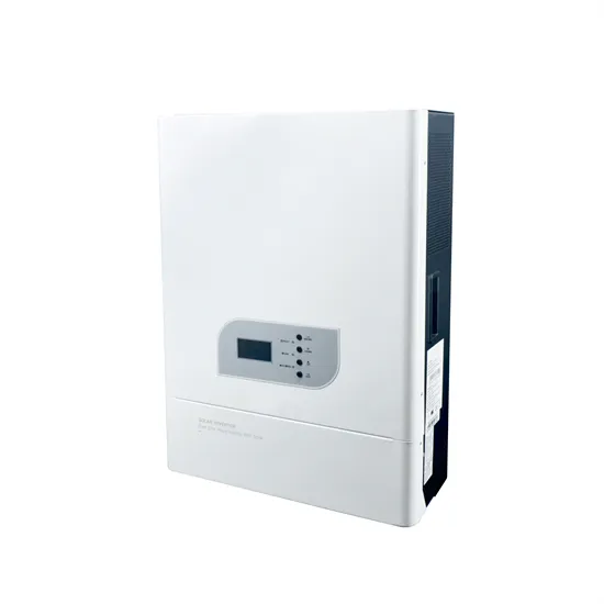
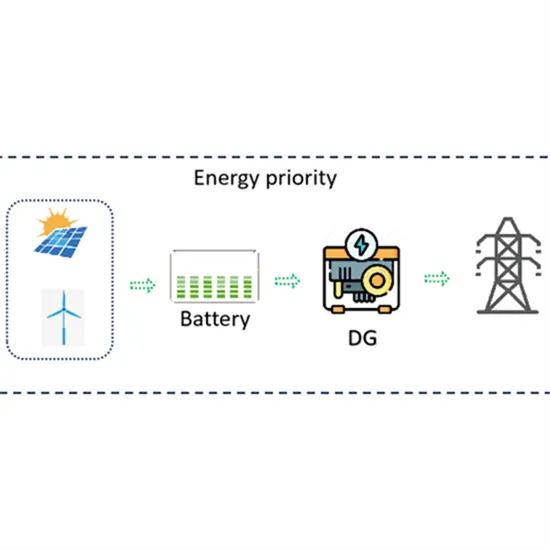
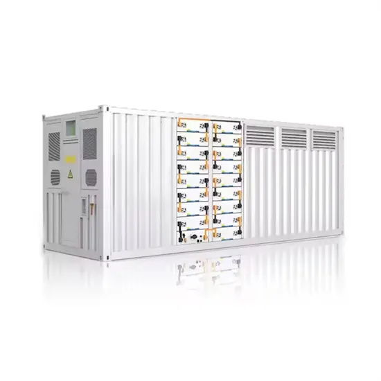
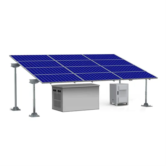
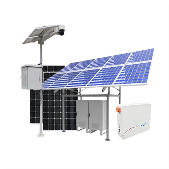
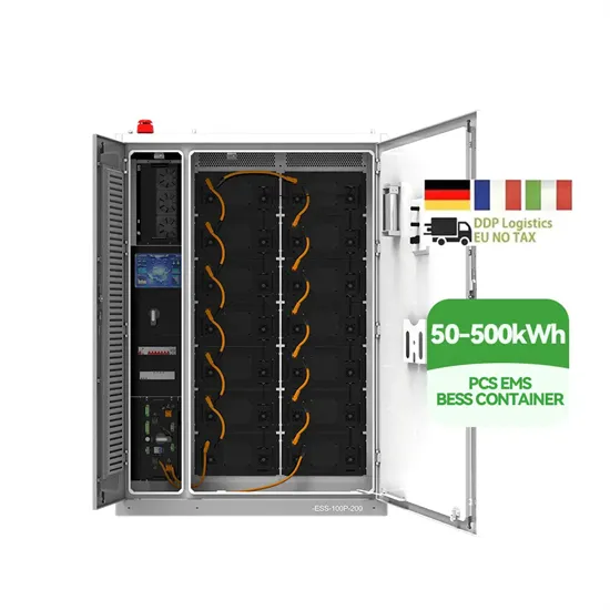
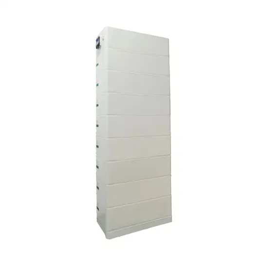
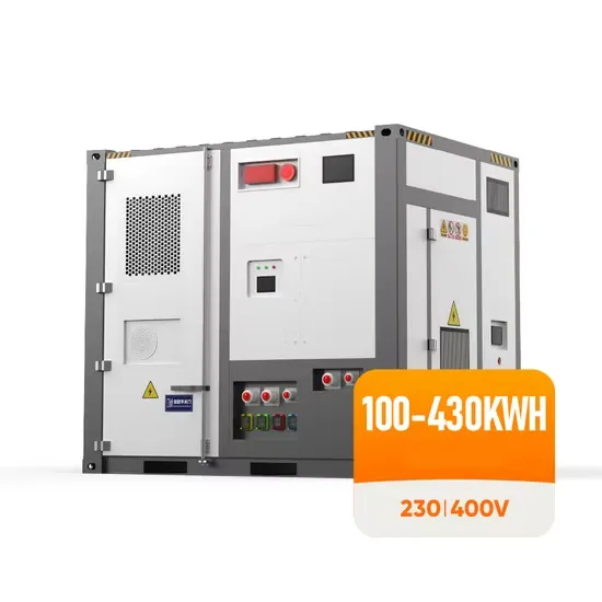
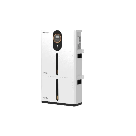
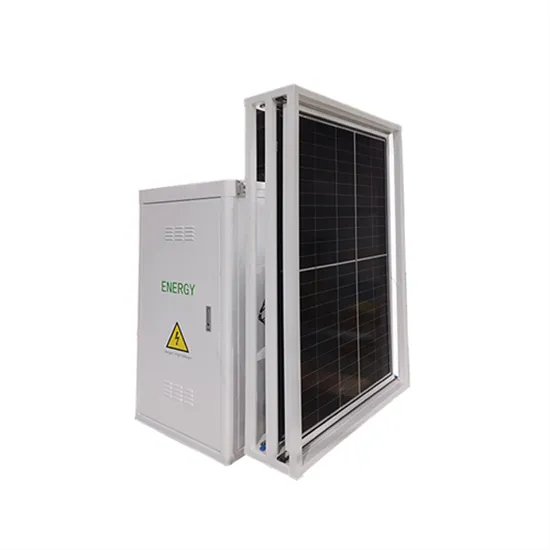
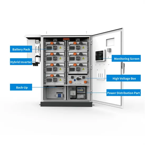
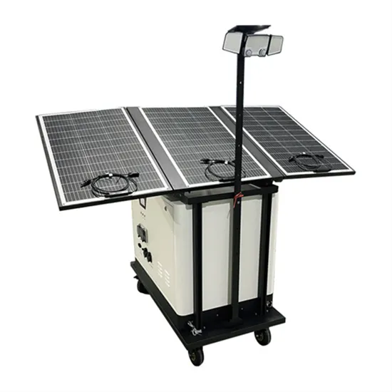
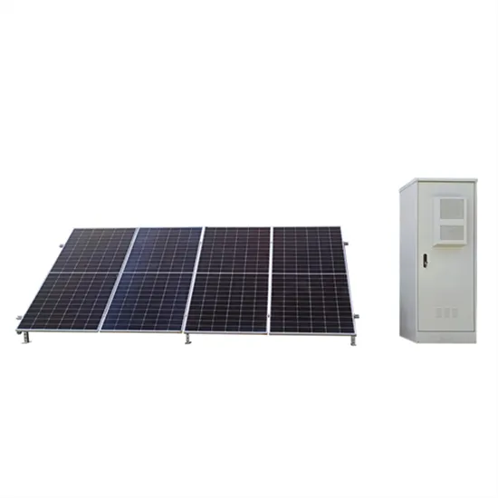
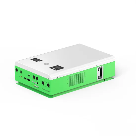
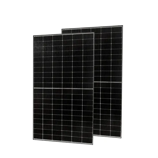
The global commercial and industrial solar energy storage battery market is experiencing unprecedented growth, with demand increasing by over 400% in the past three years. Large-scale battery storage solutions now account for approximately 45% of all new commercial solar installations worldwide. North America leads with 42% market share, driven by corporate sustainability goals and federal investment tax credits that reduce total system costs by 30-35%. Europe follows with 35% market share, where standardized industrial storage designs have cut installation timelines by 60% compared to custom solutions. Asia-Pacific represents the fastest-growing region at 50% CAGR, with manufacturing innovations reducing system prices by 20% annually. Emerging markets are adopting commercial storage for peak shaving and energy cost reduction, with typical payback periods of 3-6 years. Modern industrial installations now feature integrated systems with 50kWh to multi-megawatt capacity at costs below $500/kWh for complete energy solutions.
Technological advancements are dramatically improving solar energy storage battery performance while reducing costs for commercial applications. Next-generation battery management systems maintain optimal performance with 50% less energy loss, extending battery lifespan to 20+ years. Standardized plug-and-play designs have reduced installation costs from $1,000/kW to $550/kW since 2022. Smart integration features now allow industrial systems to operate as virtual power plants, increasing business savings by 40% through time-of-use optimization and grid services. Safety innovations including multi-stage protection and thermal management systems have reduced insurance premiums by 30% for commercial storage installations. New modular designs enable capacity expansion through simple battery additions at just $450/kWh for incremental storage. These innovations have improved ROI significantly, with commercial projects typically achieving payback in 4-7 years depending on local electricity rates and incentive programs. Recent pricing trends show standard industrial systems (50-100kWh) starting at $25,000 and premium systems (200-500kWh) from $100,000, with flexible financing options available for businesses.