 What is a boost DC AC converter?The first stage is a boost-regulator and the second stage is the boost inverter. The boost dc–ac converter is shown in Fig 5. It includes dc supply voltage Vin , input inductors L1, L2 and L3, power switches S1 – S5 , transfer capacitor C1 – C3,free-wheeling diode D1 – D5 and load resistance R.
How does a boost inverter work?The boost inverter consists of two boost converters as shown in Fig 3(b). The output of the inverter can be controlled by one of the two methods: (1) Use a duty cycle D for converter A and a duty cycle of (1- D) for converter B. (2) Use a differential duty cycle for each converter such that each converter produces a dc-biased sine wave output.
Can solar cells convert DC to AC using boost inverter?Among various possibilities, the solar cell is an instinct source of energy, which is increasingly being studied, researched and for conversion of electrical energy. In this paper we have studied dc to ac conversion technique using boost inverter with solar energy stored via PV cells in a battery as input.
Can bridgetopology be used as a boost inverter?The full bridgetopology can however be used as a boost inverter that can greater an output ac voltage higher than the input dc voltage. A traditional design methodology is the use of buck inverter. One of the characteristics of the most classical inverter is that it produces an AC output instantaneous voltage always lower than the dc input voltage.
What voltage does a boost converter use?Voltage and Current Requirements A thermal image is shown below with the boost converter operating at 150 V input and 221 V/0.9 A output (room temp, no airflow). The output ripple voltage (AC coupled) is shown in the figure below. BWL = 20 MHz, Vin = 142 V, Vout = 221 V, Iout = 0.9 A.
Which capacitor is used in boost inverter?Boost inverter uses dc link inductors to maintain a constant current, thus less capacitance value is used in dc link. Higher lifetime can be obtained by using film capacitors in boost inverters. Apart from that, source side electrolytic capacitor is replaced by multiple ac film capacitors for energy storage purpose as shown in Fig. 10, Fig.
What is a boost DC AC converter?The first stage is a boost-regulator and the second stage is the boost inverter. The boost dc–ac converter is shown in Fig 5. It includes dc supply voltage Vin , input inductors L1, L2 and L3, power switches S1 – S5 , transfer capacitor C1 – C3,free-wheeling diode D1 – D5 and load resistance R.
How does a boost inverter work?The boost inverter consists of two boost converters as shown in Fig 3(b). The output of the inverter can be controlled by one of the two methods: (1) Use a duty cycle D for converter A and a duty cycle of (1- D) for converter B. (2) Use a differential duty cycle for each converter such that each converter produces a dc-biased sine wave output.
Can solar cells convert DC to AC using boost inverter?Among various possibilities, the solar cell is an instinct source of energy, which is increasingly being studied, researched and for conversion of electrical energy. In this paper we have studied dc to ac conversion technique using boost inverter with solar energy stored via PV cells in a battery as input.
Can bridgetopology be used as a boost inverter?The full bridgetopology can however be used as a boost inverter that can greater an output ac voltage higher than the input dc voltage. A traditional design methodology is the use of buck inverter. One of the characteristics of the most classical inverter is that it produces an AC output instantaneous voltage always lower than the dc input voltage.
What voltage does a boost converter use?Voltage and Current Requirements A thermal image is shown below with the boost converter operating at 150 V input and 221 V/0.9 A output (room temp, no airflow). The output ripple voltage (AC coupled) is shown in the figure below. BWL = 20 MHz, Vin = 142 V, Vout = 221 V, Iout = 0.9 A.
Which capacitor is used in boost inverter?Boost inverter uses dc link inductors to maintain a constant current, thus less capacitance value is used in dc link. Higher lifetime can be obtained by using film capacitors in boost inverters. Apart from that, source side electrolytic capacitor is replaced by multiple ac film capacitors for energy storage purpose as shown in Fig. 10, Fig.
Aug 8, 2023 · In this paper, a new boost inverter topology and modulation strategy were provided to increase the maximum output AC voltage, gain high-efficiency power conversions. and
xcluma 12V to 220V 35W DC AC Boost Inverter Module Dual Channel Inverse Converter : Amazon : Car & MotorbikeInput DC 12V, 220V AC can be
Apr 15, 2025 · Understanding inverter power loss, selecting efficient inverters and adopting appropriate energy saving measures to improve the efficiency of
Jul 31, 2002 · This work describes a power conversion circuit topology for single-phase DC/AC boost inverter, based on the DC/DC boost converter. It mainly consists of a full-bridge boost
AC-DC Converters transform an alternating current into a direct current for reactive elements, inductors and capacitors to store it
2 days ago · One of the most important advanced and efficient technologies in converting DC electrical energy to AC is switched-capacitor multilevel inverters with reduced charging
Sep 6, 2021 · The switched boost inverter is an innovative power electronics converter topology gaining more attention with attractive fea-tures such as boost characteristics and single stage
May 15, 2019 · Abstract In this study, an integrated control strategy is proposed which can be widely used in two-stage boost inverters, and an improved two-stage boost inverter is taken as
Mar 5, 2021 · Abstract - This paper proposes a new voltage source inverter referred to as boost inverter or boost DC - AC converter. The main attribute of the new inverter topology is the fact
Description • Transform voltage from DC 12V to AC 110V 220V • Output waveform: frequency square wave • Adopt quality PCB board, durable for use • Mainly used for electronic DIY work
Feb 18, 2016 · This paper presents a new DC-AC converter which not only acts as inverter but also boosts the output voltage with respect to input. This topology is cost-effective due to
Oct 15, 2013 · In this paper we have studied dc to ac conversion technique using boost inverter with solar energy stored via PV cells in a battery as input. In this way we have enabled to
1 day ago · The proposed topology and control method are validated experimentally through a double boost 3L-NPC inverter test system, as shown in Fig. 9, and the experimental
Feb 1, 2024 · In grid integrated SPV system, inverter plays an essential role for converting DC power from SPV to utility demanded AC power. Fig. 1. Power generated from grid-connected
May 12, 2020 · In this paper, a new VSI is proposed, referred to as boost inverter, which naturally generates an output ac voltage lower or larger than the input dc voltage depending on the duty
Jun 2, 2023 · In this paper, a single-phase direct pulse width modulation (PWM) buck-boost AC–AC converter is proposed. The proposed converter utilizes a minimum number of
Aug 31, 2024 · A photovoltaic (PV) grid-connected inverter converts energy between PV modules and the grid, which plays an essential role in PV power generation systems. When compared
The 150W DC 12V to AC 110V 220V Inverter Boost Module Board Transformer Power Car Converter is a versatile electronic device designed to efficiently
Jul 3, 2015 · This paper represents a novel control scheme for buck-boost DC to AC converter in variable frequency operation. Voltage controlled dual slope delta modulator is designed to
Aug 30, 2019 · ABSTRACT--- This paper presents a new ideology called as boost inverter which converts input DC supply into AC directly without using any filter circuit. The main part of
Aug 1, 2018 · The single-stage three-phase boost inverter can provide higher value of sinusoidal AC output voltages from low-voltage DC sources without an intermediate DC–DC boost
Apr 27, 2024 · Abstract —Switched Boost Inverter (SBI) is a single stage DC to AC power converter and it is derived from the Z - source inverter employs an LC impedance network in
Description①High voltage and high frequency AC output port, can be connected with tungsten bulb, heating wire and other resistive load or voltage multiplier
Mar 8, 2022 · Here the boost converter boosting the voltage and maintain it constant with reference voltage value, next inverter invert it into AC quantity and it is finally given to the load.
Nov 6, 2024 · The boost converter-based single-stage buck/boost inverter overcomes challenges that step-up voltage limitations of traditional voltage source inverter, the increased cost and
Mar 25, 2025 · This article presents a simple high-frequency transformer (HFT) isolated buck–boost inverter designed for single-phase applications. The proposed HFT isolated
Apr 1, 2023 · In many applications, it is important for an inverter to be lightweight and of a relatively small size. This can be achieved by using a High-Frequency Inverter that involves an
Sep 14, 2021 · High-Efficiency Boost Converter Power Supply Reference Design for Automotive DC/AC Inverter Description This single-phase boost converter operates over an input voltage
Nov 13, 2024 · The output AC side voltage of traditional full-bridge inverter is lower than the input DC side voltage, which is limited in low-voltage power generation. The conventional boost
Nov 6, 2024 · Abstract: The boost converter-based single-stage buck/boost inverter overcomes challenges that step-up voltage limitations of traditional voltage source inverter, the increased
Features: Quiescent current is around 0.05A. The output waveform is a frequency square wave. The PCB board using military-grade board, mainly used for the
Nov 20, 2024 · Overview: Existing AC/DC Topologies In this section, we''re only going to discuss the boost topology, since that is the most common topology used for three-phase industrial
Dec 19, 2018 · Buy Inverter Boost Module Board, Inverter Boost Module 500W DC 12V/24V to AC 18V 0-220V-380V Power Converter Board: Power Inverters
Jul 7, 2021 · A single-phase, single-stage, differential boost inverter comprises two independently-controlled boost DC-DC converters, with the load
The first stage is a boost-regulator and the second stage is the boost inverter. The boost dc–ac converter is shown in Fig 5. It includes dc supply voltage Vin , input inductors L1, L2 and L3, power switches S1 – S5 , transfer capacitor C1 – C3, free-wheeling diode D1 – D5 and load resistance R.
The boost inverter consists of two boost converters as shown in Fig 3(b). The output of the inverter can be controlled by one of the two methods: (1) Use a duty cycle D for converter A and a duty cycle of (1- D) for converter B. (2) Use a differential duty cycle for each converter such that each converter produces a dc-biased sine wave output.
Among various possibilities, the solar cell is an instinct source of energy, which is increasingly being studied, researched and for conversion of electrical energy. In this paper we have studied dc to ac conversion technique using boost inverter with solar energy stored via PV cells in a battery as input.
The full bridgetopology can however be used as a boost inverter that can greater an output ac voltage higher than the input dc voltage. A traditional design methodology is the use of buck inverter. One of the characteristics of the most classical inverter is that it produces an AC output instantaneous voltage always lower than the dc input voltage.
Voltage and Current Requirements A thermal image is shown below with the boost converter operating at 150 V input and 221 V/0.9 A output (room temp, no airflow). The output ripple voltage (AC coupled) is shown in the figure below. BWL = 20 MHz, Vin = 142 V, Vout = 221 V, Iout = 0.9 A
Boost inverter uses dc link inductors to maintain a constant current, thus less capacitance value is used in dc link. Higher lifetime can be obtained by using film capacitors in boost inverters. Apart from that, source side electrolytic capacitor is replaced by multiple ac film capacitors for energy storage purpose as shown in Fig. 10, Fig. 12.
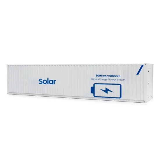
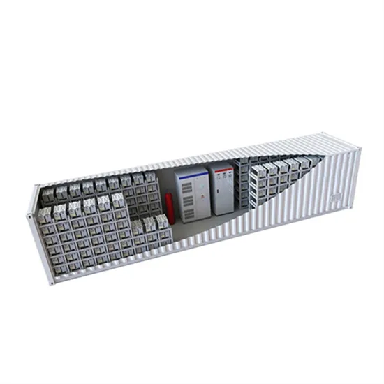
The global commercial and industrial solar energy storage battery market is experiencing unprecedented growth, with demand increasing by over 400% in the past three years. Large-scale battery storage solutions now account for approximately 45% of all new commercial solar installations worldwide. North America leads with 42% market share, driven by corporate sustainability goals and federal investment tax credits that reduce total system costs by 30-35%. Europe follows with 35% market share, where standardized industrial storage designs have cut installation timelines by 60% compared to custom solutions. Asia-Pacific represents the fastest-growing region at 50% CAGR, with manufacturing innovations reducing system prices by 20% annually. Emerging markets are adopting commercial storage for peak shaving and energy cost reduction, with typical payback periods of 3-6 years. Modern industrial installations now feature integrated systems with 50kWh to multi-megawatt capacity at costs below $500/kWh for complete energy solutions.
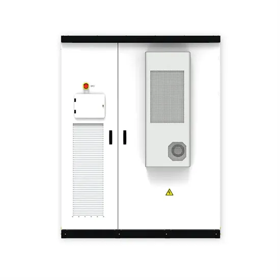
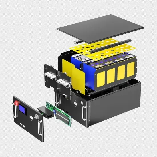
Technological advancements are dramatically improving solar energy storage battery performance while reducing costs for commercial applications. Next-generation battery management systems maintain optimal performance with 50% less energy loss, extending battery lifespan to 20+ years. Standardized plug-and-play designs have reduced installation costs from $1,000/kW to $550/kW since 2022. Smart integration features now allow industrial systems to operate as virtual power plants, increasing business savings by 40% through time-of-use optimization and grid services. Safety innovations including multi-stage protection and thermal management systems have reduced insurance premiums by 30% for commercial storage installations. New modular designs enable capacity expansion through simple battery additions at just $450/kWh for incremental storage. These innovations have improved ROI significantly, with commercial projects typically achieving payback in 4-7 years depending on local electricity rates and incentive programs. Recent pricing trends show standard industrial systems (50-100kWh) starting at $25,000 and premium systems (200-500kWh) from $100,000, with flexible financing options available for businesses.