 Full bridge inverter is a topology of H-bridge inverter used for converting DC power into AC power. The components required for conversion are two times more than that used in single phase Half bridge inverters. The circuit of a full bridge inverterconsists of 4 diodes and 4 controlled.
Mar 20, 2025 · Among the different existing inverter topologies, the full bridge or the H-bridge inverter topology is considered to be the most efficient and effective.
Feb 13, 2024 · One typical use of H-bridge circuits is to convert DC to AC in power supply applications. The control strategy of the H-bridge''s two parallel legs with two switches
Sep 6, 2020 · A three phase bridge inverter is a device which converts DC power input into three phase AC output. Like single phase inverter, it draws DC
Aug 3, 2025 · A full-bridge inverter is a power electronic circuit that converts DC to AC by strategically switching four power semiconductor devices (typically MOSFETs or IGBTs) in a
A single phase bridge DC-AC inverter is shown in Figure below. The analysis of the single phase DC-AC inverters is done taking into account following
This circuit illustrates the basic operation of a DC-DC step down buck circuit. The diode and transistor elements are modeled using ON/OFF resistances. These
Feb 13, 2024 · 2 Model One typical use of H-bridge circuits is to convert DC to AC in power supply applications. The control strategy of the H-bridge''s two parallel legs with two switches
Definition: A full bridge single phase inverter is a switching device that generates a square wave AC output voltage on the application of DC input by adjusting
A bridge inverter is defined as a type of inverter that converts DC power into AC power using a full bridge configuration of semiconductor switches, such as MOSFETs or IGBTs, and is primarily
Feb 27, 2024 · Three Phase Inverter A three phase inverter is a device that converts dc source into three phase ac output . This conversion is achieved
The three-phase full-bridge inverter topology is the simplest and most widely used structure for systems connected to the grid. It consists of three sets of
May 24, 2025 · In this article I will explain how we can build an Arduino-controlled H-Bridge sine wave inverter circuit using some easy parts. So this thing will basically convert DC into AC but
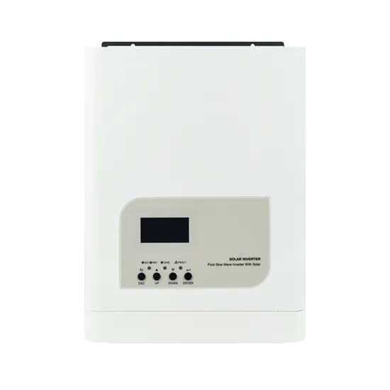
Apr 1, 2023 · The pure Sine Wave inverter has various applications because of its key advantages such as operation with very low harmonic distortion and clean power like utility-supplied
Jun 2, 2025 · A single-phase full bridge inverter is a switching device that generates a square wave AC voltage in the output on the application of DC voltage in the input by adjusting the
At IDS we have a wealth of inverter experience. We have been an ABB Partner for over 20 years and are used to supporting clients with a variety of inverter
Jun 12, 2020 · Single Phase Inverter A single-phase inverter or also called as half-bridge inverters, converters DC supply to single-phase AC supply. For
Mar 20, 2022 · Working of Full-Bridge Inverter With R Load : In the above circuit diagram, the commutating circuit of the thyristors is not shown for simplicity.
Sep 3, 2014 · Many fields use this inverter, such as motor control, UPS, and solar inverter systems. The main function of the inverter is to convert the DC power to AC power by using
Nov 20, 2019 · 2.5. Full-Bridge Inverter The inverter is a DC into AC circuit structure devices [4]. is composed of four full-bridge drive tube turns working on each band sine wave. more suitable
3 days ago · 5 Level Cascaded H-Bridge Inverter: these inverters convert the DC signal into AC having 5 voltage levels. In traditional H-bridge, the output signal
Oct 2, 2022 · 1 全桥 变换器 (Full-Bridge Converter)拓扑结构 全桥变换器 拓扑结构,如图所示: 拓扑结构分析: 输入电压 Vi 输出电压 Vo 开关组件 S1 开关组
Jan 7, 2017 · Finally, the full bridge inverter is used for high output power levels. The proposed converter uses a half bridge boost rectifier and a full bridge inverter for obtaining high output
What is a Single Phase Full Bridge Inverter? Definition: A full bridge single phase inverter is a switching device that generates a square wave AC output voltage
Dec 17, 2019 · Key learnings: Inverter Definition: An inverter is defined as a power electronics device that converts DC voltage into AC voltage, crucial for
Sep 10, 2024 · Full bridge inverter provide stable frequency and amplitude AC power, ensuring the proper operation of sensitive equipment. They offer high
Feb 15, 2023 · The single-phase full-bridge inverter is an electronic device used to convert direct current (DC) to alternating current (AC)
May 2, 2023 · Introduction to Inverters The word ''inverter'' in the context of power-electronics denotes a class of power conversion (or power conditioning) circuits that operates from a dc
May 12, 2022 · Bridge converters are used in a wide variety of linear and non-linear uses, including AC/DC power supplies, DC/DC converters, and
Sep 30, 2020 · AC/DC, DC-DC bi-directional converters for energy storage and EV applications Ramkumar S, Jayanth Rangaraju Grid Infrastructure Systems
Jun 30, 2025 · So here basically we are using two IR2184 ICs for driving two half-bridge stages which finally together become a full H-bridge inverter. This inverter is converting 220V DC into
Full Bridge Inverter vs. Half Bridge Inverter What''s the Difference? Full Bridge Inverter and Half Bridge Inverter are both types of inverters used to convert DC power to AC power. The main
Nov 21, 2020 · Inverters are electrical circuits that convert a DC supply voltage from solar panels or batteries into mains AC supply voltage upto 220 V or
Dec 24, 2017 · Dc-ac inverters are used in applications where the only source available is a fixed dc source and the system requires an ac load such as in
Voltage Source Inverters abbreviated as VSI are the type of inverter circuits that converts a dc input voltage into its ac equivalent voltage at the output. It is
Apr 1, 2023 · This application report documents the implementation of the Voltage Fed Full Bridge isolated DC-DC converter followed by the Full-Bridge DC-AC converter using TMS320F28069
Sep 10, 2024 · A full bridge inverter is a power electronics device that converts DC power to AC power. It achieves this by controlling the conduction and
Full bridge inverter is a topology of H-bridge inverter used for converting DC power into AC power. The components required for conversion are two times more than that used in single phase Half bridge inverters. The circuit of a full bridge inverter consists of 4 diodes and 4 controlled switches as shown below.
It is a common topology in power electronics conversion. The full bridge inverter consists of four switches (S1, S2, S3, S4) that work in pairs to control the direction of current flow, thereby generating an AC voltage.
Definition: A full bridge single phase inverter is a switching device that generates a square wave AC output voltage on the application of DC input by adjusting the switch turning ON and OFF based on the appropriate switching sequence, where the output voltage generated is of the form +Vdc, -Vdc, Or 0. Inverters are classified into 5 types they are
Only two modes are enough for understanding the working operation of a full bridge inverter for R load. Consider all the switches are initially off. By triggering T1 and T2, the input DC voltage (+Vdc) will appear across the load. The current flow in clockwise direction from source to the series connected load.
A three phase bridge inverter is a device which converts DC power input into three phase AC output. Like single phase inverter, it draws DC supply from a battery or more commonly from a rectifier. A basic three phase inverter is a six step bridge inverter. It uses a minimum of 6 thyristors.
PDF POWER ELECTRONICS-LAB EE-321-F - brcmcet.edu.in — The full wave bridge inverter:-Its principle of operation is similar to half bridge mode, except this time RL is connected between the both half bridge outputs. The supply voltage is E = E1 + E2. Let its function described in m terms as previous. m1.
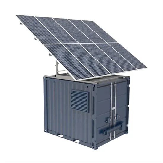
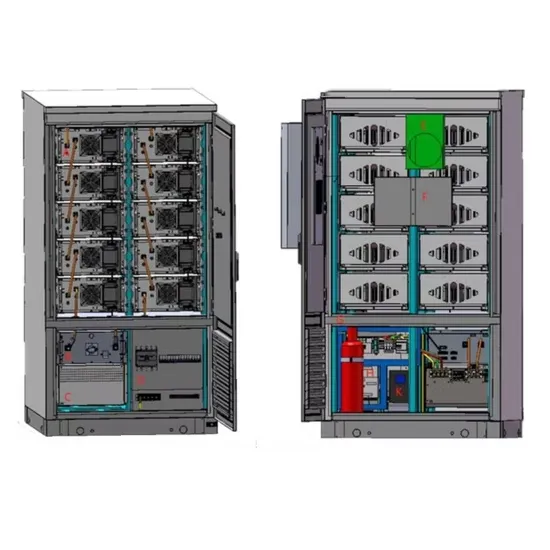
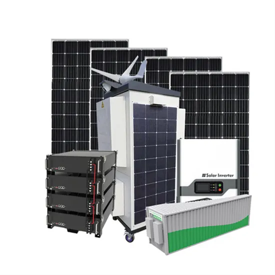
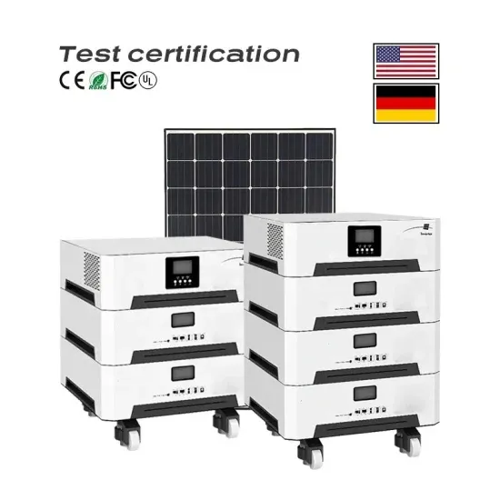
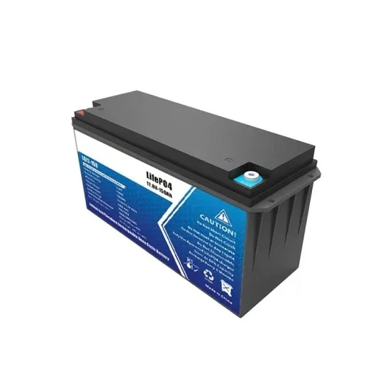
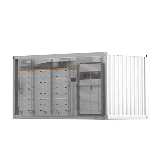
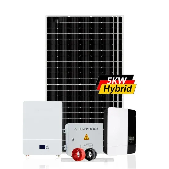
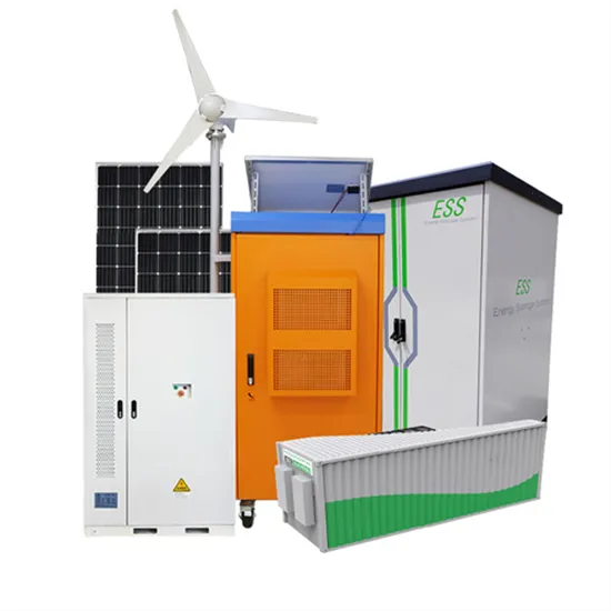
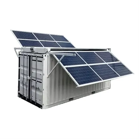
The global commercial and industrial solar energy storage battery market is experiencing unprecedented growth, with demand increasing by over 400% in the past three years. Large-scale battery storage solutions now account for approximately 45% of all new commercial solar installations worldwide. North America leads with 42% market share, driven by corporate sustainability goals and federal investment tax credits that reduce total system costs by 30-35%. Europe follows with 35% market share, where standardized industrial storage designs have cut installation timelines by 60% compared to custom solutions. Asia-Pacific represents the fastest-growing region at 50% CAGR, with manufacturing innovations reducing system prices by 20% annually. Emerging markets are adopting commercial storage for peak shaving and energy cost reduction, with typical payback periods of 3-6 years. Modern industrial installations now feature integrated systems with 50kWh to multi-megawatt capacity at costs below $500/kWh for complete energy solutions.
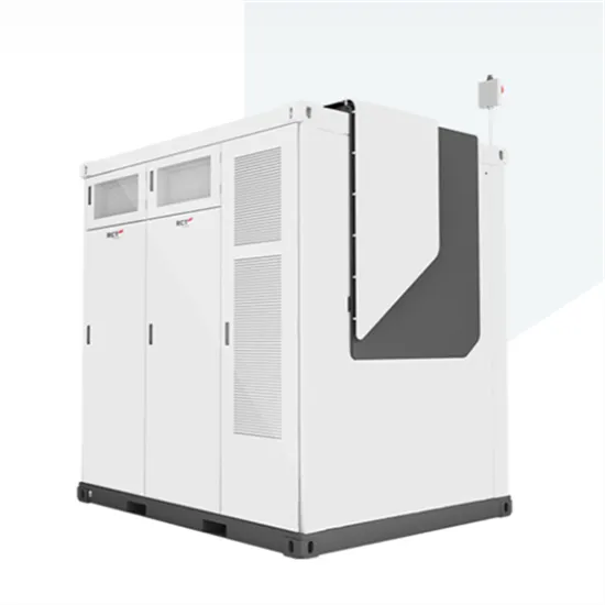
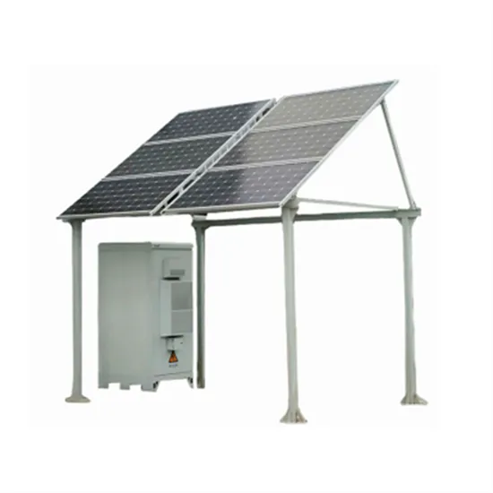
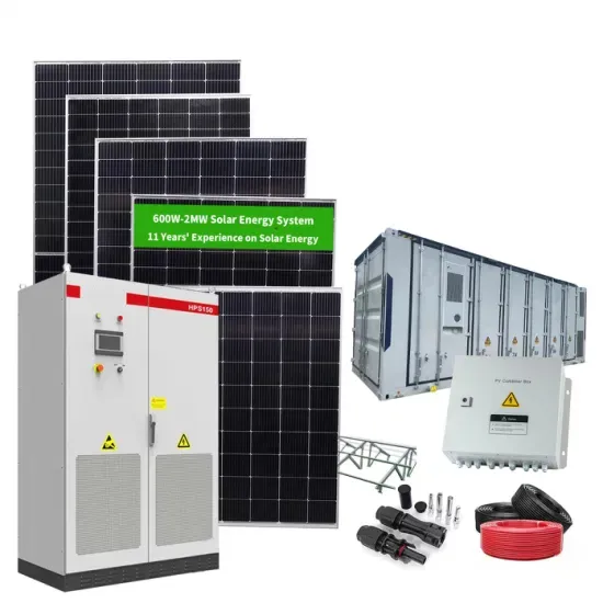
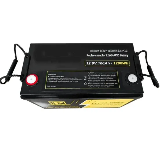
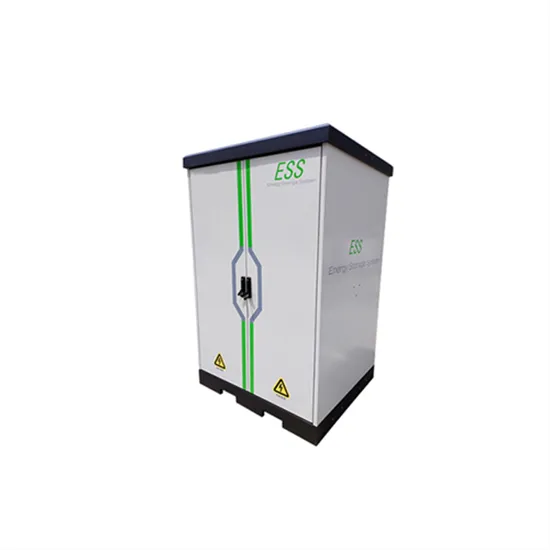
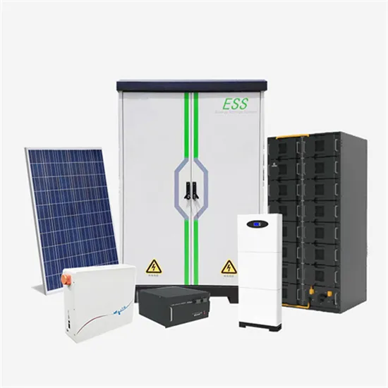
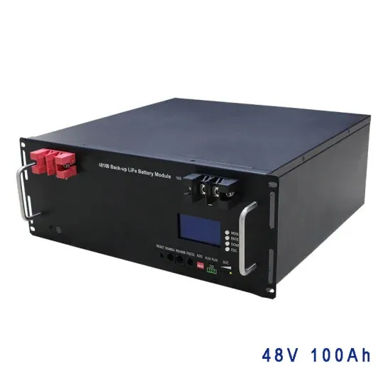
Technological advancements are dramatically improving solar energy storage battery performance while reducing costs for commercial applications. Next-generation battery management systems maintain optimal performance with 50% less energy loss, extending battery lifespan to 20+ years. Standardized plug-and-play designs have reduced installation costs from $1,000/kW to $550/kW since 2022. Smart integration features now allow industrial systems to operate as virtual power plants, increasing business savings by 40% through time-of-use optimization and grid services. Safety innovations including multi-stage protection and thermal management systems have reduced insurance premiums by 30% for commercial storage installations. New modular designs enable capacity expansion through simple battery additions at just $450/kWh for incremental storage. These innovations have improved ROI significantly, with commercial projects typically achieving payback in 4-7 years depending on local electricity rates and incentive programs. Recent pricing trends show standard industrial systems (50-100kWh) starting at $25,000 and premium systems (200-500kWh) from $100,000, with flexible financing options available for businesses.