 How a three-phase inverter is used?In this project, a three-phase inverter is used. Therefore, three voltage control signals the three different phases. are analyzed as mentioned in Section 2.2. For each of the following power modules, a specific datasheet is selected to show the step-by-step process for the power loss calculation.
What is output phase loss?Output Phase Loss is typically indicated on the drive’s HMI by some alpha or numeric designation, which varies depending on the drive. For purposes of this discussion, we’ll note it is indicated by “LF” (in the case of the Yaskawa GA800) (see Fig. 1) or a numerical code (on the ABB ACS880, “3381”).
Who are the authors of average switching loss calculation in power electronic converters?Seyyed Abbas Saremi Hasari, Ahmad Salemnia, and Mohsen Hamzeh. Applicable method for average switching loss calculation in power electronic converters. Journal of Power Electronics.
Can a simulation tool accurately estimate the power losses of an inverter?Therefore, several commercial simulation tools have been established to accurately estimate the power losses of an inverter and improve its performance. The goal of this project is to design an application capable of estimat-ing the power losses of a three-phase, hard-switched inverter using various power semi-conductor devices.
How many wires does a monophase inverter have?The cross section is also for one wire per phase. Almost all installations will have 3 wires (triphased). For very little monophased installations, there will be only 2 wires on the distance between the inverter and the injection point. During the simulation, the wiring loss is calculated at each hour, as Pwloss = Rw * I².
How do switching frequencies affect the efficiency of the inverter structure?The switching behavior of the power devices generates power losses switching frequencies will contribute to further increase the power losses . As a result, applications improve the efficiency of the inverter structure . Power losses are divided into two main categori
How a three-phase inverter is used?In this project, a three-phase inverter is used. Therefore, three voltage control signals the three different phases. are analyzed as mentioned in Section 2.2. For each of the following power modules, a specific datasheet is selected to show the step-by-step process for the power loss calculation.
What is output phase loss?Output Phase Loss is typically indicated on the drive’s HMI by some alpha or numeric designation, which varies depending on the drive. For purposes of this discussion, we’ll note it is indicated by “LF” (in the case of the Yaskawa GA800) (see Fig. 1) or a numerical code (on the ABB ACS880, “3381”).
Who are the authors of average switching loss calculation in power electronic converters?Seyyed Abbas Saremi Hasari, Ahmad Salemnia, and Mohsen Hamzeh. Applicable method for average switching loss calculation in power electronic converters. Journal of Power Electronics.
Can a simulation tool accurately estimate the power losses of an inverter?Therefore, several commercial simulation tools have been established to accurately estimate the power losses of an inverter and improve its performance. The goal of this project is to design an application capable of estimat-ing the power losses of a three-phase, hard-switched inverter using various power semi-conductor devices.
How many wires does a monophase inverter have?The cross section is also for one wire per phase. Almost all installations will have 3 wires (triphased). For very little monophased installations, there will be only 2 wires on the distance between the inverter and the injection point. During the simulation, the wiring loss is calculated at each hour, as Pwloss = Rw * I².
How do switching frequencies affect the efficiency of the inverter structure?The switching behavior of the power devices generates power losses switching frequencies will contribute to further increase the power losses . As a result, applications improve the efficiency of the inverter structure . Power losses are divided into two main categori
Sep 1, 2024 · To achieve a better quality AC output voltage, the level-phase-shifted carriers based sinusoidal pulse width modulation was applied to create a five-level PWM voltage waveform.
Disclosed is a device for detecting a phase loss in an output current in an inverter. The device includes: an output current detection unit for detecting two phases output currents from two
The difference between harmonic analysis and FFT analysis Figure 1 illustrates the frequency spectrum of active power output from an inverter. Power output from inverters includes the
Oct 30, 2023 · Excessive oversizing can negatively affect the inverter''s power production. Inverters are designed to generate AC output power up to a defined maximum which cannot
Mar 27, 2016 · The inverter first converts the input AC power to DC power and again creates AC power from the converted DC power using PWM control. The inverter outputs a pulsed
Description The Average-Value Inverter (Three-Phase) block models an average-value, full-wave inverter. It converts DC voltage to three-phase AC voltages

Apr 28, 2021 · We use an example of a residential project installed with S5-GR1P6K single phase inverter to calculate the AC cable. The AC cable on site
Aug 17, 2022 · Zero AC input current is a legit condition and voltage on AC input does no good since inverter is feeding through pass-through relay to AC input. Most inverters normally use
May 6, 2024 · AC output power limit – limits the inverter''s output power to a certain percentage of its rated power with the range of 0 to 100 (% of nominal active power). CosPhi – sets the ratio
The measurement of currents in their signal form, frequency and phase, both on the DC and AC side of the inverter, requires high accuracy, linearity and stability. Current sensors with minimal
Summary: This guide explores inverter AC phase loss challenges in industrial/commercial power systems, analyzes real-world cases, and offers actionable solutions to minimize downtime.
Jun 22, 2022 · The efficiency of an inverter refers to the amount of AC output power it provides for a given DC input. This normally falls between 85 and 95 percent, with 90 percent being the
Oct 15, 2024 · Greater resistance to inverter noise. Monitor voltage asymmetry, phase sequence, and phase loss for three-phase 3-wire or 4-wire power supplies with just one Unit. Switch
Dec 12, 2024 · Using a 1000 V Megger, test the motor and leads. For testing, set Motor Control Type = VF2pts, Output Phase Loss = No, disconnect the motor leads from the drive, run the
May 28, 2020 · Several techniques for estimating of power losses in power inverters are known. This paper presents a calculation of power losses of the inverter and following specification of
Oct 19, 2021 · 2 Losses estimation using MATLAB - Simulink For loss estimation in the three-phase inverter, the electro-thermal model in MATLAB-Simulink was created. The main part of
The reason for the inverter output phase loss is that the working principle of the inverter is to convert AC into DC, and then invert it into AC. Therefore, some small inverters input single
In this chapter we will talk about the theoretical analysis of an inverter, analysing the different configurations, the losses, the choice we have done and the models of the losses that we have
The inverter can determine whether the three-phase output is in phase loss by detecting the output current. The detection method of inverter input phase loss When the inverter works
Mar 6, 2024 · Power Loss Equations for a 3-phase inverterTI Information – Selective Disclosure
On the right side of the switching device there is the AC output of the inverter. One of the two output wires is connected directly to a connector and the other one passes through the sensor
Feb 25, 2021 · A phase loss fault is the condition caused by blown fuses, tripped circuit breakers, cable damage, open circuits, poor/loose connections and
Mar 6, 2021 · 1. Introduction Waveforms of practical inverters are non-sinusoidal and contain certain harmonics. For low- and medium-power applications, square wave or quasi-square
Mar 6, 2024 · Power Loss Equations for a 3-phase inverter TI Information – Selective Disclosure 1
Oct 28, 2019 · One critical function monitored is the health of each phase of the VSD''s output; when a fault occurs there, it is termed an Output Phase Loss. Let''s examine what triggers this
Mar 4, 2023 · The efficiency of inverter refers to the amount of AC output power it provides for a given DC input.
Jun 2, 2018 · ABSTRACT: This paper focus on modelling and simulation of single phase inverter. An inverter is a circuit that converts DC sources to AC sources. The model is implemented
Oct 19, 2018 · With a synchronous motor phase loss due to low output current at low speed no-load under this condition that cannot reach the condition of the lack of phase, in this case,
What is Inverter Efficiency? Inverter efficiency is how much Direct Current (DC) is converted into Alternating Current (AC). This is the primary function of an

Feb 27, 2024 · Three Phase Inverter A three phase inverter is a device that converts dc source into three phase ac output . This conversion is achieved
Dec 4, 2022 · As can be seen from attached, my system last night produced a phase loss error and then a stacking error in the slave inverter. So far this morning, I have been unable to clear
This example shows how to compute switching losses in a three-phase 3-level inverter, combining Specialized Power Systems and Simscape™ blocks.
Aug 12, 2023 · After the inverter starts operation, the output current is detected to be more than ten times the value of the comparison between the largest phase and the smallest phase. 1.
Nov 7, 2024 · Inverter output The AC wiring losses may simply be defined by the distance between the inverter output and the injection point (or an eventual MV transformer), and the
In this project, a three-phase inverter is used. Therefore, three voltage control signals the three different phases. are analyzed as mentioned in Section 2.2. For each of the following power modules, a specific datasheet is selected to show the step-by-step process for the power loss calculation.
Output Phase Loss is typically indicated on the drive’s HMI by some alpha or numeric designation, which varies depending on the drive. For purposes of this discussion, we’ll note it is indicated by “LF” (in the case of the Yaskawa GA800) (see Fig. 1) or a numerical code (on the ABB ACS880, “3381”).
Seyyed Abbas Saremi Hasari, Ahmad Salemnia, and Mohsen Hamzeh. Applicable method for average switching loss calculation in power electronic converters. Journal of Power Electronics,
Therefore, several commercial simulation tools have been established to accurately estimate the power losses of an inverter and improve its performance. The goal of this project is to design an application capable of estimat-ing the power losses of a three-phase, hard-switched inverter using various power semi-conductor devices.
The cross section is also for one wire per phase. Almost all installations will have 3 wires (triphased). For very little monophased installations, there will be only 2 wires on the distance between the inverter and the injection point. During the simulation, the wiring loss is calculated at each hour, as Pwloss = Rw * I².
The switching behavior of the power devices generates power losses switching frequencies will contribute to further increase the power losses . As a result, applications improve the efficiency of the inverter structure . Power losses are divided into two main categories:
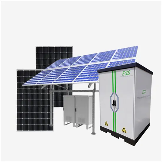
The global commercial and industrial solar energy storage battery market is experiencing unprecedented growth, with demand increasing by over 400% in the past three years. Large-scale battery storage solutions now account for approximately 45% of all new commercial solar installations worldwide. North America leads with 42% market share, driven by corporate sustainability goals and federal investment tax credits that reduce total system costs by 30-35%. Europe follows with 35% market share, where standardized industrial storage designs have cut installation timelines by 60% compared to custom solutions. Asia-Pacific represents the fastest-growing region at 50% CAGR, with manufacturing innovations reducing system prices by 20% annually. Emerging markets are adopting commercial storage for peak shaving and energy cost reduction, with typical payback periods of 3-6 years. Modern industrial installations now feature integrated systems with 50kWh to multi-megawatt capacity at costs below $500/kWh for complete energy solutions.
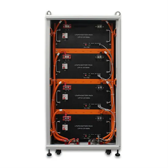
Technological advancements are dramatically improving solar energy storage battery performance while reducing costs for commercial applications. Next-generation battery management systems maintain optimal performance with 50% less energy loss, extending battery lifespan to 20+ years. Standardized plug-and-play designs have reduced installation costs from $1,000/kW to $550/kW since 2022. Smart integration features now allow industrial systems to operate as virtual power plants, increasing business savings by 40% through time-of-use optimization and grid services. Safety innovations including multi-stage protection and thermal management systems have reduced insurance premiums by 30% for commercial storage installations. New modular designs enable capacity expansion through simple battery additions at just $450/kWh for incremental storage. These innovations have improved ROI significantly, with commercial projects typically achieving payback in 4-7 years depending on local electricity rates and incentive programs. Recent pricing trends show standard industrial systems (50-100kWh) starting at $25,000 and premium systems (200-500kWh) from $100,000, with flexible financing options available for businesses.