 What is the control design of a grid connected inverter?The control design of this type of inverter may be challenging as several algorithms are required to run the inverter. This reference design uses the C2000 microcontroller (MCU) family of devices to implement control of a grid connected inverter with output current control.
What is a typical inverter?A typical inverter comprises of a full bridge that is constructed with four switches that are modulated using pulse width modulation (PWM) and an output filter for the high-frequency switching of the bridge, as shown in Figure 1. An inductor capacitor (LCL) output filter is used on this reference design.
What is a voltage source type inverter?Voltage source type inverters control the output voltage. A large-value capacitor is placed on the input DC line of the inverter in parallel. And the inverter acts as a voltage source. The inverter output needs to have characteristics of a current source. In the case of low impedance load, series reactors are needed for each phase.
Are voltage source type inverters easier to control?Voltage source type inverters are easier to control than current source type inverters. It is easier to obtain a regulated voltage than a regulated current, and voltage source type inverters can directly adjust the voltage applied to a load by varying the conduction ratio (i.e., the pulse width of a PWM signal).
How does a PV inverter state machine work?The inverter state machine then sequences to checking for DC voltage. To feed current into the grid the DC voltage (which in case of PV inverters is provided from the panel or panel plus some conditioning circuit), it must be greater than the peak of the AC voltage connected at the output of the inverter.
How does a PWM inverter work?The switching of a voltage-type PWM inverter generates a neutral-point voltage, which is divided by the capacitance distributed in a motor and appears as a motor shaft voltage. The shaft voltage damages the surfaces of a motor’s metal bearings and adversely affects its quietness and service life. Let a motor’s neutral-point voltage be
What is the control design of a grid connected inverter?The control design of this type of inverter may be challenging as several algorithms are required to run the inverter. This reference design uses the C2000 microcontroller (MCU) family of devices to implement control of a grid connected inverter with output current control.
What is a typical inverter?A typical inverter comprises of a full bridge that is constructed with four switches that are modulated using pulse width modulation (PWM) and an output filter for the high-frequency switching of the bridge, as shown in Figure 1. An inductor capacitor (LCL) output filter is used on this reference design.
What is a voltage source type inverter?Voltage source type inverters control the output voltage. A large-value capacitor is placed on the input DC line of the inverter in parallel. And the inverter acts as a voltage source. The inverter output needs to have characteristics of a current source. In the case of low impedance load, series reactors are needed for each phase.
Are voltage source type inverters easier to control?Voltage source type inverters are easier to control than current source type inverters. It is easier to obtain a regulated voltage than a regulated current, and voltage source type inverters can directly adjust the voltage applied to a load by varying the conduction ratio (i.e., the pulse width of a PWM signal).
How does a PV inverter state machine work?The inverter state machine then sequences to checking for DC voltage. To feed current into the grid the DC voltage (which in case of PV inverters is provided from the panel or panel plus some conditioning circuit), it must be greater than the peak of the AC voltage connected at the output of the inverter.
How does a PWM inverter work?The switching of a voltage-type PWM inverter generates a neutral-point voltage, which is divided by the capacitance distributed in a motor and appears as a motor shaft voltage. The shaft voltage damages the surfaces of a motor’s metal bearings and adversely affects its quietness and service life. Let a motor’s neutral-point voltage be
Feb 24, 2025 · In this paper, a method of pole and zero placement with fractional control delay for LCL-Type Grid-Connected inverter is proposed. The state feedback control is designed by
Jun 24, 2013 · Abstract The Auxiliary Resonant Commutated Pole (ARCP) in-verter has been of interest in motor drive applications that can benefit from any combination of increased
Feb 1, 2024 · The control output is the stator voltage space vector and is transformed by an inverse Park transformation from the d, q reference frame into the two-phase orthogonal
Jul 23, 2025 · This reference design is a 1.3kW totem pole power factor correction (PFC) and motor inverter for major appliances and similar products. The design illustrates a method to
Jul 1, 2018 · A low-power G m -C filter with the elliptic prototype targeting wireless application of the IEEE 802.15.4 (ZigBee) standard is presented. A modified
Mar 11, 2025 · The electronic-pole/mode changing (E-PC) mechanism includes wide flexible speed-torque ranges by operating induction motor drive (IMD) in different pole-phase
Sep 15, 2024 · Abstract—Resonant pole cancellation is usually adopted in current control or active damping to tackle the filter resonance in the LCL-type grid-connected inverter.
Mar 11, 2025 · Abstract: The electronic-pole/mode changing (E-PC) mechanism includes wide flexible speed-torque ranges by operating induction motor drive (IMD) in different pole-phase
Sep 12, 2023 · Fig. 15 Experimental output of inverter voltage during EPC for (a) Instantaneous EPC (b) GEPC technique; experimental stator current during pole changing (c) Instantaneous
Aug 28, 2018 · Frequency Response of the Active Inverter - Continued So, back to the frequency response of the active load inverter, we find that if |p1| < z1, then the -3dB frequency is
PV inverter, a CM resonant circuit can be created between. is directly connected with the negative pole. PV negative directly connected to the ground through The GP inverter
More categories › Hybrid Inverter Combos Plug & Play Portable Power Systems High Voltage Inverters & Batteries More categories › Battery cables, chargers
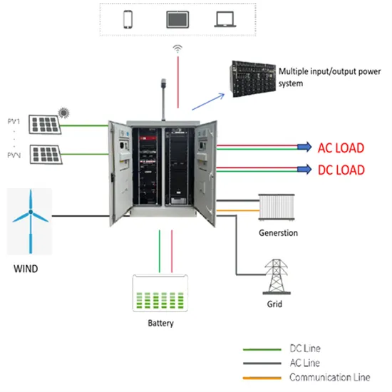
Fig. 30 presents basic voltage waveforms of dual- inverter system with synchronized PWM; Figs. 31 show spectra of the pole and phase voltages of
Jan 15, 2024 · This technical note introduces the working principle of the grid-following inverter and presents an implementation with TPI 8032.
Feb 27, 2024 · In a three-phase inverter, the pole voltage, which represents the voltage applied to the load, is equivalent to the pole voltage in a half-phase
Jul 23, 2025 · Up to 1.3kW power output, 75kHz switching frequency, digital control totem pole boost PFC with power factor > 0.95 and < 5% THD from medium to full load over entire
Jul 23, 2025 · Description This reference design is a 1.3kW totem pole power factor correction (PFC) and motor inverter for major appliances and similar products. The design illustrates a
May 26, 2023 · The total number of the switching pulses provided for any quarter cycle of voltage source inverter fundamental voltage is limited in the selective harmonic elimination method,
Dual-inverter configuration has been attracting increasing attention, especially in motor drives, for its advantages in fault tolerance, multilevel modulation effect,
May 11, 2022 · Grid Connected Inverter Reference Design Description This reference design implements single-phase inverter (DC/AC) control using a C2000TM microcontroller (MCU).
Feb 24, 2025 · We often implement such PWM based on a comparison between a triangle wave and a reference voltage. (We can use any ∆ wave, e.g. a sawtooth, but the harmonic content
Oct 30, 2023 · Abstract— This paper proposes a DC-Decoupled based multi- phase inverter (DCDMI) topology for electronic-pole changing (E-PC) induction motor drive (IMD) system.
May 27, 2014 · However, the pulse voltage value of the inverter output side voltage remains unchanged at about 2 that of the power supply. ∗5 The braking torque indicated is a short
Jul 26, 2018 · It is easier to obtain a regulated voltage than a regulated current, and voltage source type inverters can directly adjust the voltage applied to a load by varying the
Abstract—This article proposes a generalized inverter design framework for a variable-pole induction machine (IM). It quanti-fies the advantages of pole changing and a high number of
Jun 1, 2016 · The standard single-phase three-level voltage source inverter (VSI) for uninterruptible power supply systems consist of a pulse width modulation
For the proposed drive configuration the DC link voltage required for 2 inverters is half of the DC link voltage used in the neutral point clamped inverter. The
Jul 1, 2011 · On the other hand, adaptive control of 4-leg inverters has not yet been discussed in the literature. This paper proposes pole-placement control strategy, via state feedback, for 4
An SVPWM scheme for a 3 level voltage generation is proposed in this paper. An open end winding induction motor, fed from a 3 level voltage realised by cascading 2 two level inverters.
Nov 12, 2023 · The overall system dynamics including power, voltage, current controller, inverter, and line impedance are given in state space based small signal modeling section when it is in
Feb 27, 2024 · This technical guide aims to clarify the main aspects concerning applications of low voltage (≤ 690 V) induction motors with static frequency inverters supply, for frames ≤ IEC
The control design of this type of inverter may be challenging as several algorithms are required to run the inverter. This reference design uses the C2000 microcontroller (MCU) family of devices to implement control of a grid connected inverter with output current control.
A typical inverter comprises of a full bridge that is constructed with four switches that are modulated using pulse width modulation (PWM) and an output filter for the high-frequency switching of the bridge, as shown in Figure 1. An inductor capacitor (LCL) output filter is used on this reference design.
Voltage source type inverters control the output voltage. A large-value capacitor is placed on the input DC line of the inverter in parallel. And the inverter acts as a voltage source. The inverter output needs to have characteristics of a current source. In the case of low impedance load, series reactors are needed for each phase.
Voltage source type inverters are easier to control than current source type inverters. It is easier to obtain a regulated voltage than a regulated current, and voltage source type inverters can directly adjust the voltage applied to a load by varying the conduction ratio (i.e., the pulse width of a PWM signal).
The inverter state machine then sequences to checking for DC voltage. To feed current into the grid the DC voltage (which in case of PV inverters is provided from the panel or panel plus some conditioning circuit), it must be greater than the peak of the AC voltage connected at the output of the inverter.
The switching of a voltage-type PWM inverter generates a neutral-point voltage, which is divided by the capacitance distributed in a motor and appears as a motor shaft voltage. The shaft voltage damages the surfaces of a motor’s metal bearings and adversely affects its quietness and service life. Let a motor’s neutral-point voltage be e0.
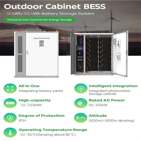
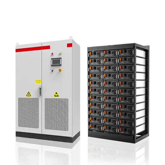
The global commercial and industrial solar energy storage battery market is experiencing unprecedented growth, with demand increasing by over 400% in the past three years. Large-scale battery storage solutions now account for approximately 45% of all new commercial solar installations worldwide. North America leads with 42% market share, driven by corporate sustainability goals and federal investment tax credits that reduce total system costs by 30-35%. Europe follows with 35% market share, where standardized industrial storage designs have cut installation timelines by 60% compared to custom solutions. Asia-Pacific represents the fastest-growing region at 50% CAGR, with manufacturing innovations reducing system prices by 20% annually. Emerging markets are adopting commercial storage for peak shaving and energy cost reduction, with typical payback periods of 3-6 years. Modern industrial installations now feature integrated systems with 50kWh to multi-megawatt capacity at costs below $500/kWh for complete energy solutions.
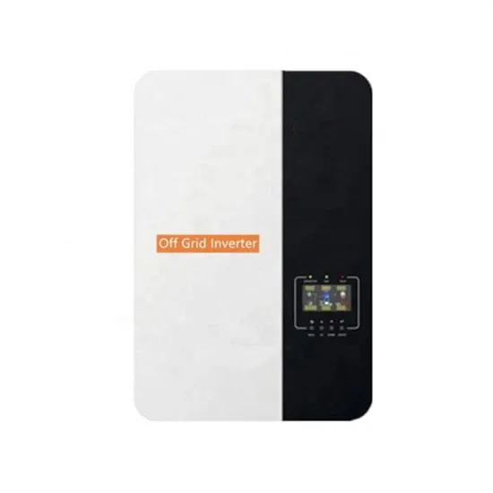
Technological advancements are dramatically improving solar energy storage battery performance while reducing costs for commercial applications. Next-generation battery management systems maintain optimal performance with 50% less energy loss, extending battery lifespan to 20+ years. Standardized plug-and-play designs have reduced installation costs from $1,000/kW to $550/kW since 2022. Smart integration features now allow industrial systems to operate as virtual power plants, increasing business savings by 40% through time-of-use optimization and grid services. Safety innovations including multi-stage protection and thermal management systems have reduced insurance premiums by 30% for commercial storage installations. New modular designs enable capacity expansion through simple battery additions at just $450/kWh for incremental storage. These innovations have improved ROI significantly, with commercial projects typically achieving payback in 4-7 years depending on local electricity rates and incentive programs. Recent pricing trends show standard industrial systems (50-100kWh) starting at $25,000 and premium systems (200-500kWh) from $100,000, with flexible financing options available for businesses.