 What is an example of a full-bridge inverter?Example: The full-bridge inverter has a switching sequence that produces a square wave voltage across a series RL load. The switching frequency is 60 Hz, Vs=100 V, R=10 Ω, and L=25 mH. Determine (a) an expression for load current, (b) the power absorbed by the load, and (c) the average current in the dc source.
What is the switching frequency of a full-bridge inverter?The switching frequency is 60 Hz, Vs=100 V, R=10 Ω, and L=25 mH. Determine (a) an expression for load current, (b) the power absorbed by the load, and (c) the average current in the dc source. Example: The full-bridge inverter has a switching sequence that produces a square wave voltage across a series RL load.
What is the voltage and current rating of an inverter module?The module has voltage and current rating of 650 V and 400 A, respectively. The nominal switching frequency of the inverter is 10 KHz. The rest of information, such as the switching energy losses, collector-emitter voltage drop, and thermal parameters, which are necessary to calculate the power losses can be found in the datasheet. Fig. 10.
What is the nominal switching frequency of the inverter?The nominal switching frequency of the inverter is 10 KHz. The rest of information, such as the switching energy losses, collector-emitter voltage drop, and thermal parameters, which are necessary to calculate the power losses can be found in the datasheet. Fig. 10. Drivetrain configuration with the control scheme for each converter stage. Table 3.
What is a square wave inverter circuit?In a square wave inverter circuit we will typically find the waveform as shown below across the power devices, which deliver the current and voltage to the relevant transformer winding as per the mosfet conduction rate using this square wave:.
How does a 3 phase inverter work?However, most 3-phase loads are connected in wye or delta, placing constraints on the instantaneous voltages that can be applied to each branch of the load. For the wye connection, all the “negative” terminals of the inverter outputs are tied together, and for the detla connection, the inverter output terminals are cascaded in a ri
What is an example of a full-bridge inverter?Example: The full-bridge inverter has a switching sequence that produces a square wave voltage across a series RL load. The switching frequency is 60 Hz, Vs=100 V, R=10 Ω, and L=25 mH. Determine (a) an expression for load current, (b) the power absorbed by the load, and (c) the average current in the dc source.
What is the switching frequency of a full-bridge inverter?The switching frequency is 60 Hz, Vs=100 V, R=10 Ω, and L=25 mH. Determine (a) an expression for load current, (b) the power absorbed by the load, and (c) the average current in the dc source. Example: The full-bridge inverter has a switching sequence that produces a square wave voltage across a series RL load.
What is the voltage and current rating of an inverter module?The module has voltage and current rating of 650 V and 400 A, respectively. The nominal switching frequency of the inverter is 10 KHz. The rest of information, such as the switching energy losses, collector-emitter voltage drop, and thermal parameters, which are necessary to calculate the power losses can be found in the datasheet. Fig. 10.
What is the nominal switching frequency of the inverter?The nominal switching frequency of the inverter is 10 KHz. The rest of information, such as the switching energy losses, collector-emitter voltage drop, and thermal parameters, which are necessary to calculate the power losses can be found in the datasheet. Fig. 10. Drivetrain configuration with the control scheme for each converter stage. Table 3.
What is a square wave inverter circuit?In a square wave inverter circuit we will typically find the waveform as shown below across the power devices, which deliver the current and voltage to the relevant transformer winding as per the mosfet conduction rate using this square wave:.
How does a 3 phase inverter work?However, most 3-phase loads are connected in wye or delta, placing constraints on the instantaneous voltages that can be applied to each branch of the load. For the wye connection, all the “negative” terminals of the inverter outputs are tied together, and for the detla connection, the inverter output terminals are cascaded in a ri
Mar 24, 2023 · The before-collapse field looking the same to the inverter with or without syncadv modification means we already calculated the field angle for syncadv=10: it''s vector (id=-60,
Jun 23, 2021 · The before-collapse field looking the same to the inverter with or without syncadv modification means we already calculated the field angle for syncadv=10: it''s vector (id=-60,
Dec 27, 2023 · by johu » Mon Oct 18, 2021 4:44 pm Ok, nevermind. The inverter can use the full bus voltage. It is really strange. With FW off I get the oscillation at around 300 Hz but I can
Jan 22, 2023 · The before-collapse field looking the same to the inverter with or without syncadv modification means we already calculated the field angle for syncadv=10: it''s vector (id=-60,
Jun 23, 2021 · However, the inverter might not be outputting the same field (in its viewpoint) when configured with syncadv=20, thus we''ll look at bexander''s 2021-06-12 graph.
Feb 24, 2025 · A half-bridge inverter requires only two devices and can synthesize a positive and a negative output {+ 1 VDC, − 1 VDC } but no zero state, while a full-bridge inverter can
Jun 13, 2021 · My understanding is that the controller should output the requested torque by driving a certain current through the motor and this up until the difference between supply
May 15, 2025 · Example: The full-bridge inverter has a switching sequence that produces a square wave voltage across a series RL load. The switching frequency is 60 Hz, Vs=100 V,
Oct 22, 2022 · by johu » Mon Oct 18, 2021 4:44 pm Ok, nevermind. The inverter can use the full bus voltage. It is really strange. With FW off I get the oscillation at around 300 Hz but I can
Dec 21, 2021 · Whenever PWM is employed in an inverter for enabling a sine wave output, inverter voltage drop becomes a major issue, especially if the parameters are not calculated
Jan 29, 2024 · by johu » Mon Oct 18, 2021 4:44 pm Ok, nevermind. The inverter can use the full bus voltage. It is really strange. With FW off I get the oscillation at around 300 Hz but I can
Mar 31, 2010 · EEC 118 Lecture #4: CMOS Inverters Rajeevan Amirtharajah University of California, Davis Jeff Parkhurst Intel Corporation
Solis is one of the world''s largest and most experienced manufacturers of solar inverters supplying products globally for multinational utility companies,
Nov 15, 2023 · The resultant Symmetrical Cascaded HB (SCHB) inverter designed in this paper can normally adapt to single-stage AC/DC power conversion, and the output voltage can be
Feb 14, 2025 · 10PDN was sized to be like the inverter. The transient analysis with a shorted input (A and B to Vin), had different results except for fall time;
Jun 5, 2021 · My setup using a Prius Gen 3 inverter with a Toyota/Lexus MGR gives poor performance when entering field weakening. tom3141 have the same issue with the MGR but
Jun 26, 2023 · Micro inverter can be found as current source inverter (CSI) or voltage source inverter (VSI) • AC/DC converter: – When used with a DC/DC controller as a current source
Dec 25, 2023 · by johu » Mon Oct 18, 2021 4:44 pm Ok, nevermind. The inverter can use the full bus voltage. It is really strange. With FW off I get the oscillation at around 300 Hz but I can
Nov 27, 2022 · My goal is to get an SPWM + inverter block that takes in a voltage demand input and produces it at the output. Any ideas to why am I getting half
Oct 16, 2021 · Ok, nevermind. The inverter can use the full bus voltage. It is really strange. With FW off I get the oscillation at around 300 Hz but I can punch through it with more throttle. Then
Jul 24, 2024 · rs in comparison to 2-level inverters is halved due to the better voltage approximation opportunity [1]. In addition the switching loss-es are lower due to the halved
Dec 1, 2024 · The VVC adjusts the dc-link voltage in relation to the motor stator voltage, that in turns varies with the torque and speed [1, 5]. With the aid of VVC, the dc-link voltage is
Example: The full-bridge inverter has a switching sequence that produces a square wave voltage across a series RL load. The switching frequency is 60 Hz, Vs=100 V, R=10 Ω, and L=25 mH. Determine (a) an expression for load current, (b) the power absorbed by the load, and (c) the average current in the dc source.
The switching frequency is 60 Hz, Vs=100 V, R=10 Ω, and L=25 mH. Determine (a) an expression for load current, (b) the power absorbed by the load, and (c) the average current in the dc source. Example: The full-bridge inverter has a switching sequence that produces a square wave voltage across a series RL load.
The module has voltage and current rating of 650 V and 400 A, respectively. The nominal switching frequency of the inverter is 10 KHz. The rest of information, such as the switching energy losses, collector-emitter voltage drop, and thermal parameters, which are necessary to calculate the power losses can be found in the datasheet. Fig. 10.
The nominal switching frequency of the inverter is 10 KHz. The rest of information, such as the switching energy losses, collector-emitter voltage drop, and thermal parameters, which are necessary to calculate the power losses can be found in the datasheet. Fig. 10. Drivetrain configuration with the control scheme for each converter stage. Table 3.
In a square wave inverter circuit we will typically find the waveform as shown below across the power devices, which deliver the current and voltage to the relevant transformer winding as per the mosfet conduction rate using this square wave:
However, most 3-phase loads are connected in wye or delta, placing constraints on the instantaneous voltages that can be applied to each branch of the load. For the wye connection, all the “negative” terminals of the inverter outputs are tied together, and for the detla connection, the inverter output terminals are cascaded in a ring.
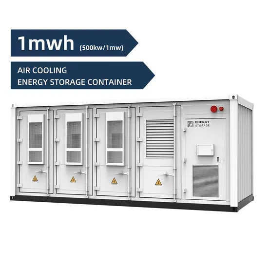
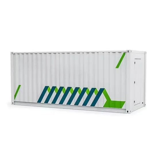
The global commercial and industrial solar energy storage battery market is experiencing unprecedented growth, with demand increasing by over 400% in the past three years. Large-scale battery storage solutions now account for approximately 45% of all new commercial solar installations worldwide. North America leads with 42% market share, driven by corporate sustainability goals and federal investment tax credits that reduce total system costs by 30-35%. Europe follows with 35% market share, where standardized industrial storage designs have cut installation timelines by 60% compared to custom solutions. Asia-Pacific represents the fastest-growing region at 50% CAGR, with manufacturing innovations reducing system prices by 20% annually. Emerging markets are adopting commercial storage for peak shaving and energy cost reduction, with typical payback periods of 3-6 years. Modern industrial installations now feature integrated systems with 50kWh to multi-megawatt capacity at costs below $500/kWh for complete energy solutions.
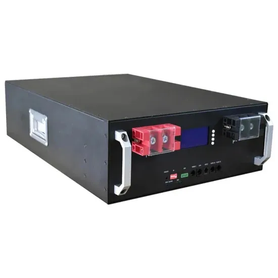
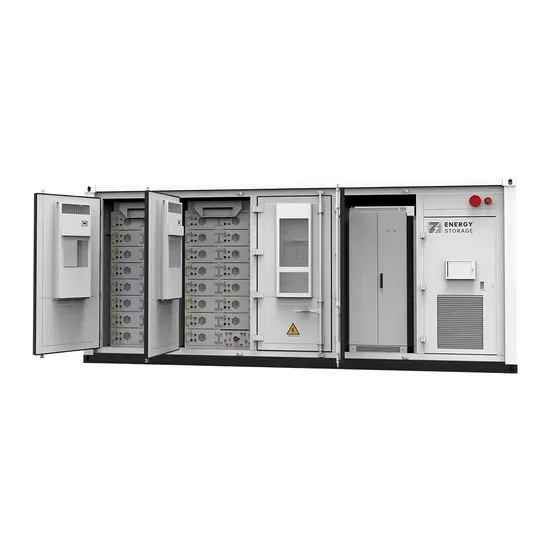
Technological advancements are dramatically improving solar energy storage battery performance while reducing costs for commercial applications. Next-generation battery management systems maintain optimal performance with 50% less energy loss, extending battery lifespan to 20+ years. Standardized plug-and-play designs have reduced installation costs from $1,000/kW to $550/kW since 2022. Smart integration features now allow industrial systems to operate as virtual power plants, increasing business savings by 40% through time-of-use optimization and grid services. Safety innovations including multi-stage protection and thermal management systems have reduced insurance premiums by 30% for commercial storage installations. New modular designs enable capacity expansion through simple battery additions at just $450/kWh for incremental storage. These innovations have improved ROI significantly, with commercial projects typically achieving payback in 4-7 years depending on local electricity rates and incentive programs. Recent pricing trends show standard industrial systems (50-100kWh) starting at $25,000 and premium systems (200-500kWh) from $100,000, with flexible financing options available for businesses.