 How a MOSFET is connected to an inverter?The inverter output voltage is taken from the common drain terminals. The transistors are connected in a manner that ensures that only one of the MOSFETs conducts when the input is stable at a low or high voltage; this is due to the use of the complementary arrangement.
Which is better MOSFET or inverter?the resistive load. Here, MOSFET is active load and inverter with active load gives a better performance than the inverter.Enhancement load-Load transistor can be operated either, in saturation region or in linear region, depending on the bias voltage applied tits gate terminal. The saturated enhancement load inverter is shown.
Is a MOSFET enough for a steady-state inverter?Although the MOSFET parameters and the number of devices placed in parallel in each switch position of the inverter may be sufficient to allow for steady-state operation at maximum load and charging, it is also essential to consider the case when the UPS output is short-circuited.
How many amps can a MOSFET handle?Take the example of the MOSFET in the image above, here the maximum tolerable voltage Vdss of the specified MOSFET is 75V, and maximum tolerable current Id is 209 amps, when operated with proper heatsink. It means this MOSFET can be safely used for all applications where the load wattage is not more than 14000 watts.
What is a Power MOSFET?A Power MOSFET is a type of switching technology that is typically preferred for power electronics designs because it can be switched efficiently at high voltages and high frequencies.
Why do MOSFETs require a diode?Each power MOSFET in an inverter, such as one in an inverter, requires a diode to protect it from reverse current from an inductive load. Fast recovery diodes (FRDs) are used due to the high switching frequency of MOSFETs, and their properties can also help increase efficien
How a MOSFET is connected to an inverter?The inverter output voltage is taken from the common drain terminals. The transistors are connected in a manner that ensures that only one of the MOSFETs conducts when the input is stable at a low or high voltage; this is due to the use of the complementary arrangement.
Which is better MOSFET or inverter?the resistive load. Here, MOSFET is active load and inverter with active load gives a better performance than the inverter.Enhancement load-Load transistor can be operated either, in saturation region or in linear region, depending on the bias voltage applied tits gate terminal. The saturated enhancement load inverter is shown.
Is a MOSFET enough for a steady-state inverter?Although the MOSFET parameters and the number of devices placed in parallel in each switch position of the inverter may be sufficient to allow for steady-state operation at maximum load and charging, it is also essential to consider the case when the UPS output is short-circuited.
How many amps can a MOSFET handle?Take the example of the MOSFET in the image above, here the maximum tolerable voltage Vdss of the specified MOSFET is 75V, and maximum tolerable current Id is 209 amps, when operated with proper heatsink. It means this MOSFET can be safely used for all applications where the load wattage is not more than 14000 watts.
What is a Power MOSFET?A Power MOSFET is a type of switching technology that is typically preferred for power electronics designs because it can be switched efficiently at high voltages and high frequencies.
Why do MOSFETs require a diode?Each power MOSFET in an inverter, such as one in an inverter, requires a diode to protect it from reverse current from an inductive load. Fast recovery diodes (FRDs) are used due to the high switching frequency of MOSFETs, and their properties can also help increase efficien

Dec 22, 2024 · The inverter consists of an isolated DC-DC step-up stage to convert the battery voltage to a HV DC bus voltage, followed by an inverter stage that produces a sinusoidal
Jul 28, 2025 · Each power MOSFET in an inverter, for example, requires a diode to protect it from being damaged by the reverse current from an inductive load. Because the MOSFETs switch
Mar 25, 2024 · It simply and clearly demonstrates the bootstrapping principle of the high-side suspension driving circuit. Among them, C1 is the bootstrap capacitor, VD1 is the bootstrap
Series MOSFETs Can''t Always Handle More Voltage We could conceivably use identical MOSFETs with maximum voltage ratings of 50 V; by placing them in series, they would each
Feb 24, 2012 · Inverter Circuits: MOSFET inverters, including resistive load n-MOS, active load n-MOS, and CMOS inverters, are fundamental in digital
Mar 13, 2024 · The smaller input voltage at which first slope occur is called the input low voltage '' '' and the larger input voltage at which second slope occur is called the input high voltage '' ''. s
The maximum inrush current the inverter can withstand without damage The upper and lower output voltage limits The upper and lower input voltage limits
Jan 15, 2025 · Being MOS devices with very high gate impedance, power MOSFETs can be damaged by static discharge during handling, testing or installation into a circuit. ESD damage
Feb 4, 2025 · With a resistor pull-up, the pull-up current, iPU, is (VDD - vOUT)/R and the pull-down current, iPD, is the MOSFET drain current. This current depends on the gate-to-source
Sep 28, 2024 · A MOSFET is a voltage-controlled device in mosfet inverter that works by applying a voltage to the Gate to control the current between the
Mar 24, 2021 · NEXT GENERATION INVERTER TRENDS Many customers are looking at ways to reduce overall systems cost, not only in the inverter, but the number of panels and
Aug 17, 2020 · For example, the withstand voltage of a MOSFET can be simply expressed as: Withstand voltage = maximum electric breakdown field × depletion region thickness ÷ 2 (The
Jun 21, 2025 · The Drain-Source Voltage (V_DS) represents the maximum voltage that can be applied between the MOSFET''s drain and source terminals without causing damage. For high
Jan 25, 2025 · If this current exceeds the maximum short-circuit current that the inverter can handle, the inverter may suffer damage. The maximum short
Jun 10, 2022 · DESCRIPTION Two kinds of voltage ratings are provided for MOSFETs in their datasheets - VDS and VGS. For each, both absolute maximum and rated voltages are
Nov 18, 2016 · From the above figure, we can see that the input voltage of the inverter is equal to the gate to source voltage of nMOS transistor and output
5 days ago · Inverter to control motors is necessary for industrial robotic applications that contribute factory automation. We introduce the approach of
Feb 2, 2016 · This article revisits some of the basic principles of power supplies and then addresses how MOSFETs—the power stage of any switching-voltage regulator—affect
Sep 9, 2021 · In high reliability, high performance applications, like electrical/ hybrid vehicles, isolated gate drivers need to ensure the isolation barrier stays intact under all circumstances.
Nov 28, 2024 · Take the example of the MOSFET in the image above, here the maximum tolerable voltage Vdss of the specified MOSFET is 75V, and
Ans: (b) Sol: As MOSFET have internally antiparallel diodes, MOSFET can not withstand reverse voltage, due to which MOSFET can not be as current source inverter (CSI). Q29: A single
Feb 16, 2024 · The system is programmed using an Arduino Uno to generate PWM signals and to keep 120 degrees phase displacement among each phase. Three step-up transformers are
Apr 29, 2024 · SiC MOSFET Short Circuit Application Note Implementing protection against short-circuit events is critical for designing safe and reliable power electronic systems. In both
Aug 19, 2025 · The Drain-Source Voltage (V_DS) represents the maximum voltage that can be applied between the MOSFET''s drain and source terminals without causing damage. For high
Feb 4, 2025 · As an example, consider the MOSFET inverter circuit shown at the top of the next page with an n-channel MOSFET pull-down and a resistor pull-up. The MOSFET is
Dec 2, 2020 · What is MOSFET Avalanche Rating MOSFET avalanche rating is the maximum tolerable energy (millijoule) a MOSFET can withstand, when its
Mar 20, 2025 · Transformers step up the voltage for equipment. In a grid-tied inverter, transformers are used to isolate the current and match the inverter
Nov 17, 2023 · An inverter is a device that converts direct current (DC) to alternating current (AC) at the specified voltage and frequency. Inverters
Sep 9, 2021 · This article investigates a gate driver''s isolation withstand performance through the intentional destruction of IGBT/ MOSFET power switches. In high reliability, high performance
May 19, 2023 · While the dielectric voltage withstand test is widely used, the real objective of the test is often misunderstood, which may lead to incomplete testing or misleading test results.
Feb 20, 2025 · 4th-generation SiC MOSFETs offer the improved short-circuit withstand time required for EV traction inverters and other equipment through further refinements to ROHM''s
Jun 20, 2024 · Such a topology reduces voltage stress on components and energy losses to improve the inverter design efficiency. Multilevel inverter classes include three-level, five-level,
May 25, 2025 · In addition, the CoolSiCTM MOSFET enables inverter integration into the motor, which is challenging with state-of-the-art IGBTs. Furthermore, fast short-circuit protec-tion can

The inverter output voltage is taken from the common drain terminals. The transistors are connected in a manner that ensures that only one of the MOSFETs conducts when the input is stable at a low or high voltage; this is due to the use of the complementary arrangement.
the resistive load. Here, MOSFET is active load and inverter with active load gives a better performance than the inverter .Enhancement load-Load transistor can be operated either, in saturation region or in linear region, depending on the bias voltage applied t its gate terminal. The saturated enhancement load inverter is shown
Although the MOSFET parameters and the number of devices placed in parallel in each switch position of the inverter may be sufficient to allow for steady-state operation at maximum load and charging, it is also essential to consider the case when the UPS output is short-circuited.
Take the example of the MOSFET in the image above, here the maximum tolerable voltage Vdss of the specified MOSFET is 75V, and maximum tolerable current Id is 209 amps, when operated with proper heatsink. It means this MOSFET can be safely used for all applications where the load wattage is not more than 14000 watts.
A Power MOSFET is a type of switching technology that is typically preferred for power electronics designs because it can be switched efficiently at high voltages and high frequencies.
Each power MOSFET in an inverter, such as one in an inverter, requires a diode to protect it from reverse current from an inductive load. Fast recovery diodes (FRDs) are used due to the high switching frequency of MOSFETs, and their properties can also help increase efficiency.
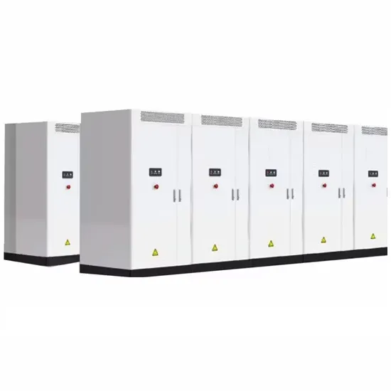
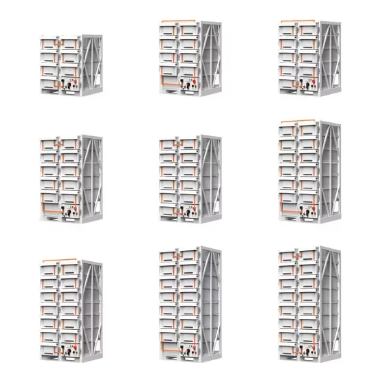
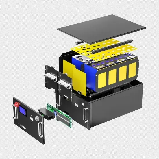
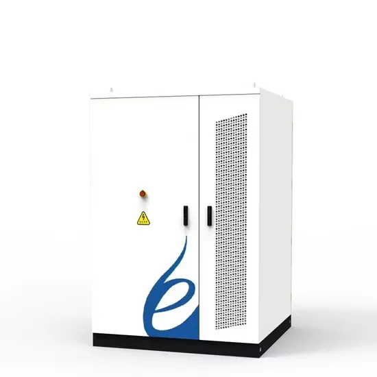
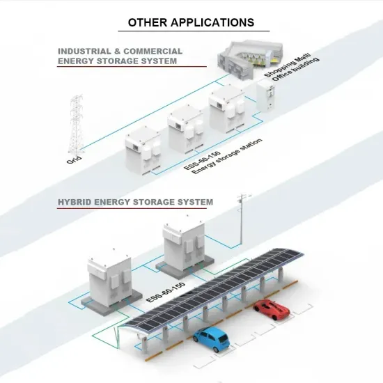
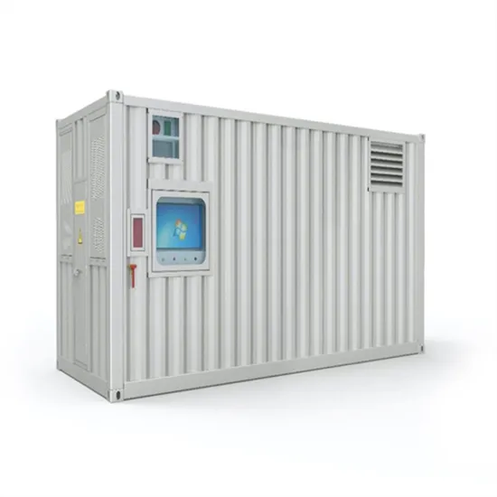
The global commercial and industrial solar energy storage battery market is experiencing unprecedented growth, with demand increasing by over 400% in the past three years. Large-scale battery storage solutions now account for approximately 45% of all new commercial solar installations worldwide. North America leads with 42% market share, driven by corporate sustainability goals and federal investment tax credits that reduce total system costs by 30-35%. Europe follows with 35% market share, where standardized industrial storage designs have cut installation timelines by 60% compared to custom solutions. Asia-Pacific represents the fastest-growing region at 50% CAGR, with manufacturing innovations reducing system prices by 20% annually. Emerging markets are adopting commercial storage for peak shaving and energy cost reduction, with typical payback periods of 3-6 years. Modern industrial installations now feature integrated systems with 50kWh to multi-megawatt capacity at costs below $500/kWh for complete energy solutions.
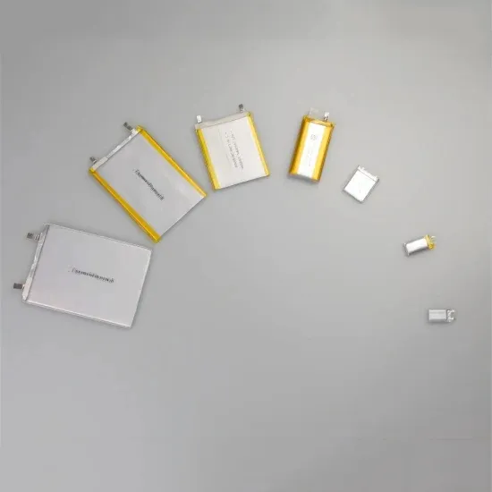
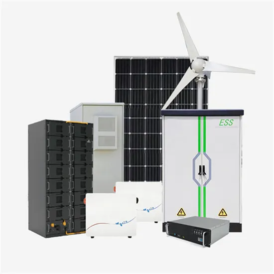
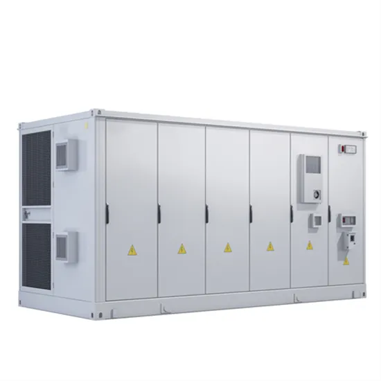
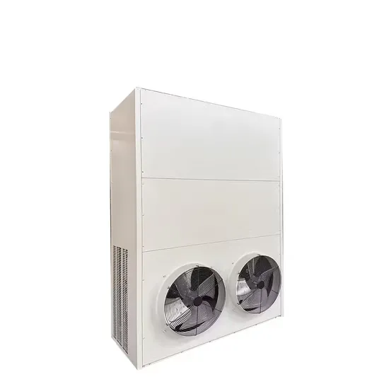
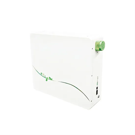
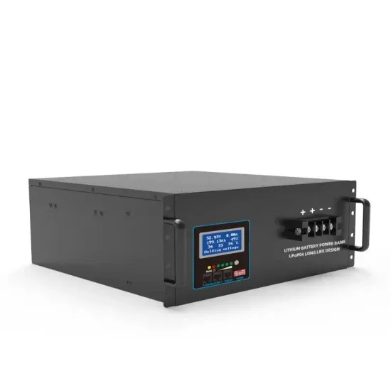
Technological advancements are dramatically improving solar energy storage battery performance while reducing costs for commercial applications. Next-generation battery management systems maintain optimal performance with 50% less energy loss, extending battery lifespan to 20+ years. Standardized plug-and-play designs have reduced installation costs from $1,000/kW to $550/kW since 2022. Smart integration features now allow industrial systems to operate as virtual power plants, increasing business savings by 40% through time-of-use optimization and grid services. Safety innovations including multi-stage protection and thermal management systems have reduced insurance premiums by 30% for commercial storage installations. New modular designs enable capacity expansion through simple battery additions at just $450/kWh for incremental storage. These innovations have improved ROI significantly, with commercial projects typically achieving payback in 4-7 years depending on local electricity rates and incentive programs. Recent pricing trends show standard industrial systems (50-100kWh) starting at $25,000 and premium systems (200-500kWh) from $100,000, with flexible financing options available for businesses.